232
POWERHEAD
POWERHEAD ASSEMBLY
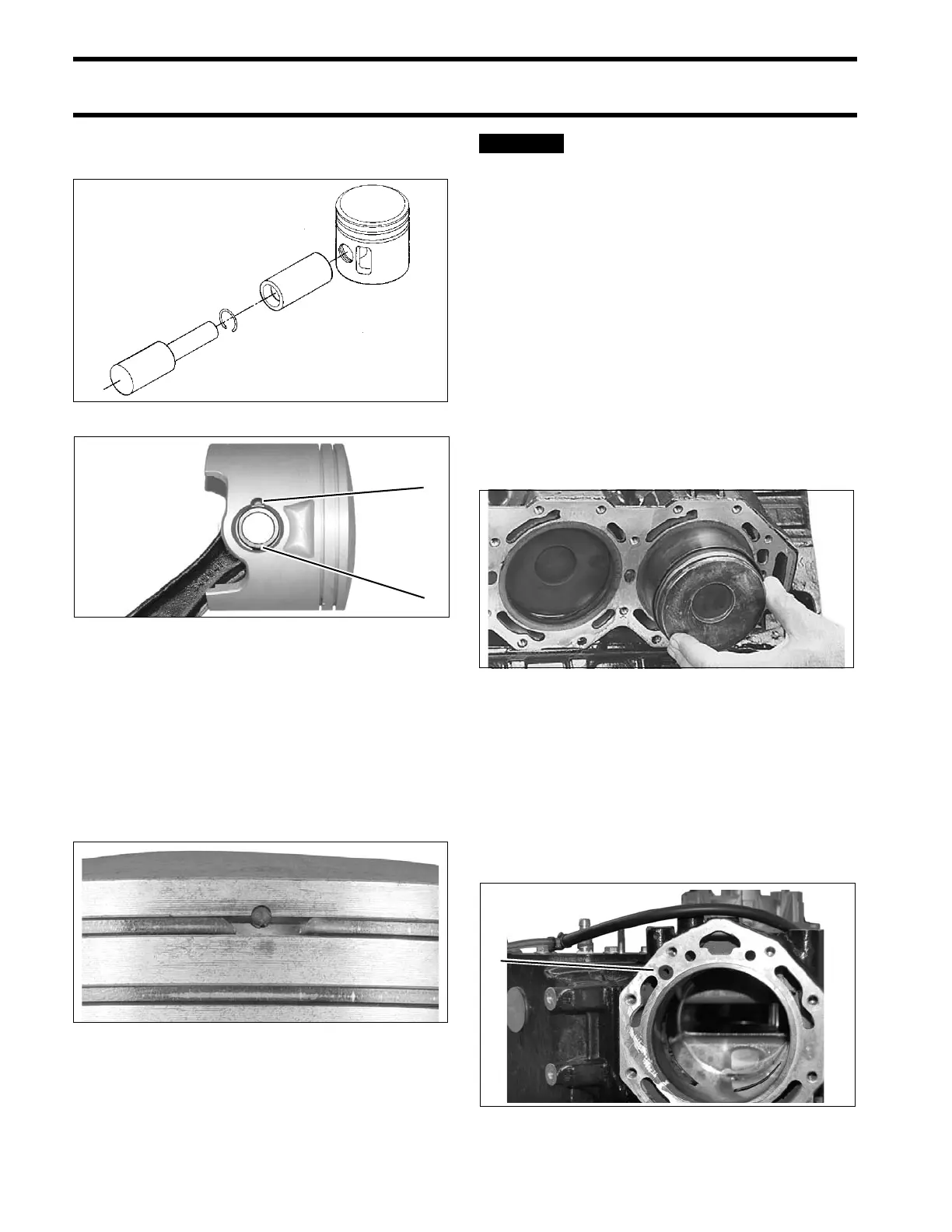
in each wrist pin hole. Gap of retaining ring faces
away from notch in piston.
Installing Pistons
When all pistons and connecting rods are assem-
bled, install piston ring sets. Be sure rings are
installed in the cylinder used to test ring end gap.
Refer to POWERHEAD INSPECTION on p. 226.
IMPORTANT: Be sure gap of ring fits squarely
around dowel pin.
Before continuing, make sure that
all Gel-Seal II has been removed from the cyl-
inder block and crankcase mating flanges. If
traces of hardened Gel-Seal II are left, main
bearings could be misaligned. Refer to CYLIN-
DER BLOCK CLEANING on p. 225.
Coat pistons, rings, cylinder walls, and ring com-
pressor with outboard lubricant.
Center connecting rod in piston and locate piston
rings on dowel pins. Place appropriate ring com-
pressor on piston.
Slide piston and rod assembly into the correct cyl-
inder, as marked during disassembly. Guide con-
necting rod through cylinder block to avoid
scratching cylinder wall.
Cylinder Head Installation
Lightly coat both sides of a new cylinder head
gasket with Gasket Sealing Compound. Place
gasket on cylinder block following instructions
printed on gasket.
Apply soapy water to water dam and insert into
block.
DR1641
1. Gap in retaining ring
2. Notch in piston
000756
002048
49435
1. Water dam 006965