373
TRIM AND TILT
ELECTRICAL CIRCUIT TESTS
14
Monitor motor RPM and current draw.
The motor shaft must rotate clockwise, as viewed
from the pump end, when positive (+) is applied to
the blue lead, and negative (–) is connected to
green lead.
The motor shaft must rotate counterclockwise, as
viewed from the pump end, when positive (+) is
applied to the green lead, and negative (–) is
applied to the blue lead.
If test results vary, replace the motor.
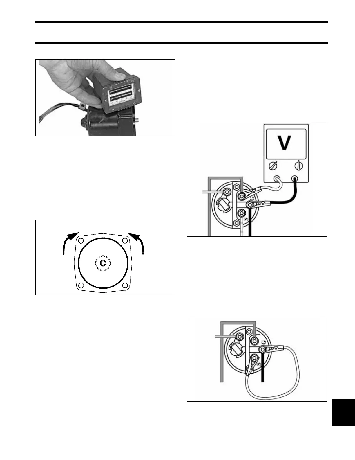
Trim Gauge Test
STEP 1
Turn key switch ON. Using a voltmeter, check for
voltage between the trim gauge “I” and “G” termi-
nals.
• If no voltage, check condition of instrument har-
ness, key switch, and engine 20 A fuse.
• If voltage, go to STEP 2.
STEP 2
Remove the white/tan lead from the trim gauge
“S” terminal. With key switch ON, gauge should
indicate full-trim DOWN position. Now connect a
jumper wire between terminals “S” and “G.”
Gauge should indicate full-trim UP position.
• If results are different, replace the trim gauge.
• If results agree, refer to Trim Sender Test.
30957
DR4238r
Green lead (+)
Blue lead (-)
Blue lead (+)
Green lead (-)
DRC6245
DRC6246A