IONPURE
®
G2 DISPLAY BOARD – IP-POWERDSP-G2
IP-POWERDSP-G2MAN Rev 1 Page 10 of 25
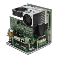
Figure 5: Connections to Multiple G2 Power Controllers
2.4 Power Controller Setup
2.4.1 DC Output Current Range Selection
To limit the possibility of applying excessive current to a CEDI module, it is recommended to
select an appropriate output current range with DIP switch SW1 of the G2 Power Controller as
described in Figure 6. Select the current range that can limit the current closest to the
maximum value that could be required by the module. Table 3 of the G2 Power Controller
manual lists the maximum DC currents required by each module.
Figure 6: Current Range Selection DIP Switch
 Loading...