IONPURE
®
G2 DISPLAY BOARD – IP-POWERDSP-G2
IP-POWERDSP-G2MAN Rev 1 Page 2 of 25
Table of Contents
DISCLAIMER STATEMENT .................................................................................................................. 4
PROPRIETARY RIGHTS STATEMENT ................................................................................................ 4
MANUAL REVISION HISTORY............................................................................................................. 4
1 INTRODUCTION ............................................................................................................................. 5
1.1 Caution and Warning Messages ................................................................................................ 5
1.2 General Description ................................................................................................................... 5
2 INSTALLATION............................................................................................................................... 7
2.1 Requirements............................................................................................................................. 7
2.2 Panel Mount............................................................................................................................... 8
2.3 Connections ............................................................................................................................... 8
2.3.1 Connections to a Single G2 Power Controller....................................................................... 8
2.3.2 Connections to Multiple G2 Power Controllers ..................................................................... 9
2.4 Power Controller Setup ............................................................................................................ 10
2.4.1 DC Output Current Range Selection .................................................................................. 10
2.4.2 Unit ID Selection................................................................................................................. 11
3 OPERATION.................................................................................................................................. 12
3.1 Control/Navigation Keys........................................................................................................... 12
3.2 Menu Structure......................................................................................................................... 13
4 GETTING STARTED ..................................................................................................................... 23
4.1 Initial Startup ............................................................................................................................ 23
4.2 Output Current Adjustment ...................................................................................................... 23
5 TROUBLESHOOTING................................................................................................................... 24
APPENDIX – UL AND CE COMPLIANCE........................................................................................... 25
List of Figures
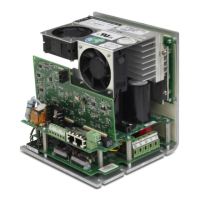
Figure 1: G2 Display Board.................................................................................................................... 5
Figure 2: G2 Display Dimensions........................................................................................................... 7
Figure 3: Panel Cutout Dimensions ....................................................................................................... 8
Figure 4: Connections to a Single G2 Power Controller......................................................................... 9
Figure 5: Connections to Multiple G2 Power Controllers...................................................................... 10
 Loading...