Do you have a question about the Ewellix CAHB-2 Series and is the answer not in the manual?
Manual provides important information for safe and efficient actuator operation.
Explains safety precautions identified by symbols and signal words indicating hazard severity.
Manufacturer not liable for damage resulting from manual disregard, unintended use, or unauthorized modifications.
Warranty terms are those contained in the manufacturer's terms and conditions of sale.
Ewellix Customer Service provides technical information and answers questions.
Details safety precautions and information for safe installation, operation, and maintenance.
Outlines responsibilities of owner/processor for safe operation, including risk assessment and personnel training.
Discusses the importance and maintenance of safety equipment for safe operation.
Specifies environmental conditions like temperature range and humidity for actuator operation.
Lists operating voltages and limits for different actuator designs (E and S) and versions.
Details the information provided on the actuator's product label for E and S designs.
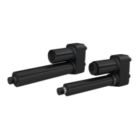
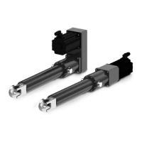
Provides an overview of the CAHB-20 E actuator and its types.
Offers a concise overview of the actuator's components and operation.
Highlights special features like overload protection, integrated controller, and absolute position sensor.
Details the construction of the motor, gear unit, integrated control unit, and linear unit.
Illustrates the connection points for the actuator to power supply or external devices.
Describes available options like limit switches, potentiometers, encoders, and manual override.
Provides safety guidelines for transporting actuators to prevent damage.
Specifies conditions for proper storage of actuators to maintain their integrity.
Advises on selecting an appropriate installation location, avoiding harsh environments.
Describes the procedure for attaching the actuator using hinge heads.
Lists essential inspections and tests to be performed by an electrician before initial operation.
Details wiring schemes for connecting the actuator to the power supply for different designs.
Specifies the Baud rates supported for CAN bus communication.
Defines default CAN-IDs and explains CAN-ID distribution and synchronous mode.
Describes the structure and meaning of feedback messages transmitted via CAN bus.
Details the format and content of control messages for actuator operation.
Provides examples of feedback and control messages for CAN bus communication.
Highlights safety precautions during actuator operation, including risk of crushing.
Emphasizes ensuring the stroke area is clear of persons or objects before operation.
Describes normal operation, clutch activation, and adherence to limits.
Outlines steps to take in hazardous situations, including stopping movement and cutting power.
Instructs to separate the actuator from the power supply after use.
States that only genuine spare parts should be used and replacement is by Ewellix.
Presents a maintenance plan with tasks, intervals, and responsible personnel.
Details cleaning, inspections, and visual condition checks to be performed.
Lists steps to be performed after maintenance, before restarting the actuator.
Provides a table of symptoms, checkpoints, possible causes, and actions for troubleshooting.
Instructs to follow installation steps before restarting after fixing a malfunction.
Describes the procedure for dismantling the actuator from application elements.
Guides on proper disposal of actuator components according to environmental regulations.
| Brand | Ewellix |
|---|---|
| Model | CAHB-2 Series |
| Category | Controller |
| Language | English |