18
CAHB-20 series
nal control.
4.6 Options
Ifnotspeciedotherwise,theoptionslistedbelowareavail-
able for the entire series of CAHB-2xE and S linear
actuators.
4.6.1 Limit switch
E design
The limit switch makes it possible to control the stroke of the
linear unit by internal setting. Contact the Ewellix to adjust
the setting of limit switch.
Remark: Limit switch is not available for CAHB-20 E
S design
Entire series of CAHB2xS integrated endstop based on the
absolute position feed back
The endstop position can be adjusted by CAN bus J1939 or
by I/O (⮑7.4Controlmessage,page27)
4.6.2 Potentiometer (E design only)
The potentiometer provides a signal indicating the position
ofthelinearactuator.Theelectricalspecicationasonthe
datasheet.
• Linear actuator with potentiometer unit: colours of wire are
white,greenandbrown(⮑Fig.15).
Retract Extend
Green
Brown
White
POT
Limit + POT:
White
Green Brown
0 CW 10K
Fig. 15
Potentiometer
4.6.3 Absolute analog position output
E design
The absolute analog position sensor is a multitude non-con-
tact magnetic sensor. It provides a signal indicating the posi-
tionofthelinearactuator.theoutputsignalis0~5VDCvolt-
age(currentoutput5mAmax).Theelectricalspecication
andresolutionrefertodatesheet,thewiresconnectingrefer
to 6.4.1 Wiring scheme.
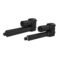
NOTE
WhenactuatorwithPOTortheanalogoutput,don’trotatethepush
tube 45 degree and don’t connect to power before the actuator is
installed into device (see picture below) Otherwise would demage
the potentiometer or the analog sensor components.
WARNING
S design
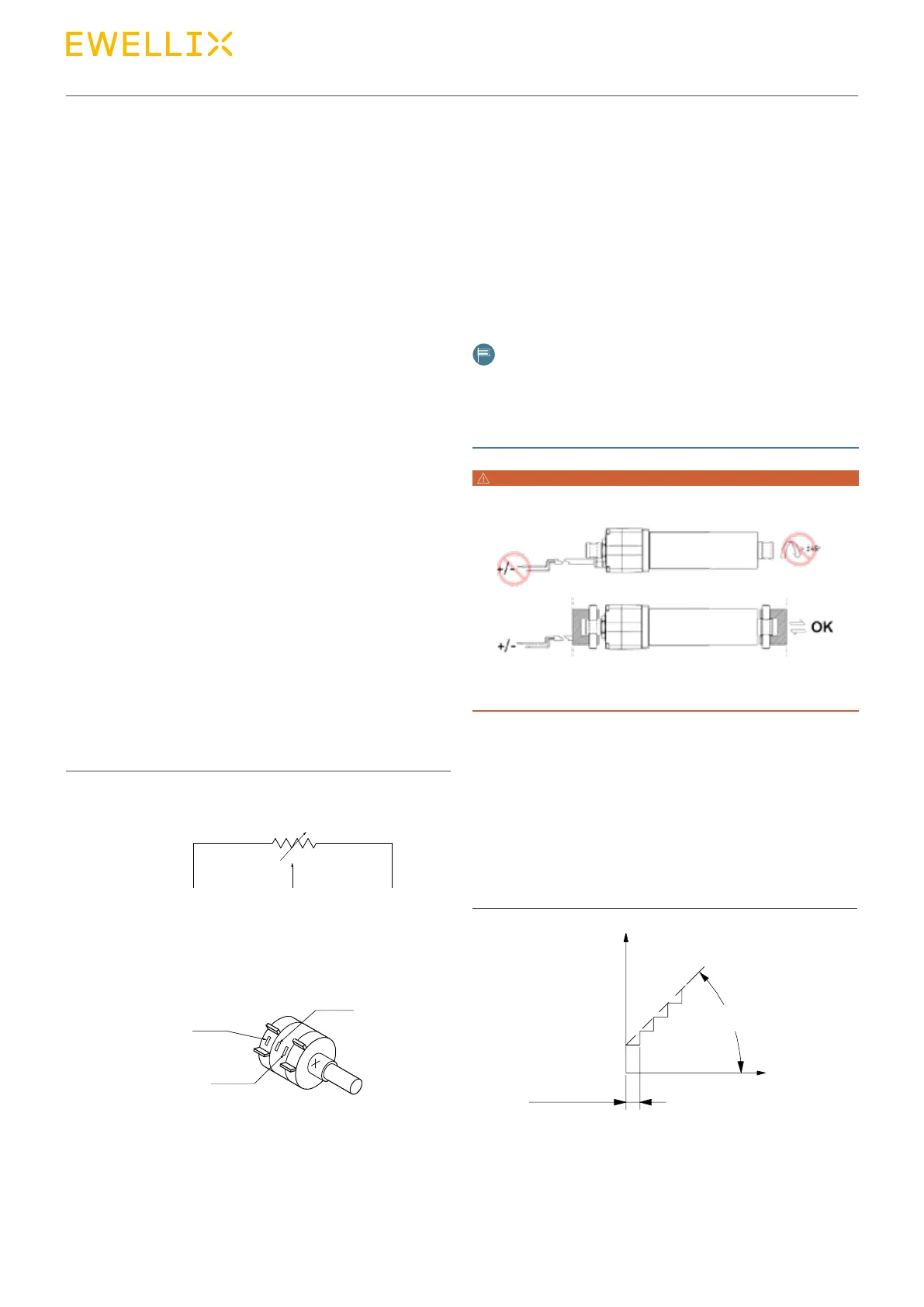
The absolute analog position output is simulated by smart
PCBA. It provides a signal indicating the position of the lin-
earactuator.Theoutputsignalis0~5or0~10VDC(current
output 15 mA max) depending of ordering key selection. The
electricalspecicationandresolutionrefertodatasheet,the
wires connecting refer to 6.4.3 S design wiring scheme
output(V)
5
4,5
0,5
0
resolution
tan(α)=outputrelationto
displacement(V/mm)
α
displacement (mm)
Fig. 16
 Loading...