Maintenance
14.Oncestep11isachieved,holdthethreadedrod
endwithatoolandtightenthelocknutagainst
thestandardnut.DoNotallowthecabletoturn
whenthenutsaretightened.
15.Afteradjustingthebrakesonbothsidesofthe
mower,cyclethebrakehandleaminimumofsix
timestoallowthecabletoseatintothesheath
andmountingtabs.
16.Readjustbothbrakesfollowingtheprocedurein
steps
10through14.
17.Ifabrakecomponenthasbeenremovedor
replaced,seethestepsbelow;otherwiseproceed
tostep18.
BurnishingtheBrakeProcedure:
A.Cleartheareaofanyammablematerial
beforestartingtheburnishingprocess.
B.Rotatethedrivewheelreleasehandletothe
“operating”position.RefertotheDrive
WheelReleaseValvessectioninOperation.
C.Applytheparkbrake.
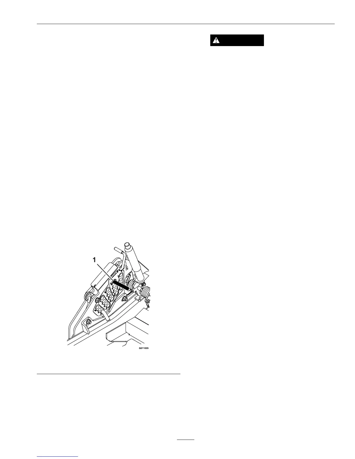
D.Installa1/2x6inch(approx.)rodorbolt
throughthe2inchheightofcuthole(see
Figure31).
Figure31
1.2inchheightofcutlocation
E.Startthemowerwhileintheoperatorposition.
WARNING
Enginemustberunninganddrivewheels
mustbeturningsoadjustmentscanbe
performed.Contactwithmovingpartsor
hotsurfacesmaycausepersonalinjury.
Keepngers,hands,andclothingclearof
rotatingcomponentsandhotsurfaces.
F.Releasetheparkbrakesothehandlerestson
the1/2x6inchrodorbolt.
G.Movethethrottletohighidle.
H.Movebothmotioncontrolleverstothefull
forwardpositionandholdfor15seconds.
I.Movebothmotioncontrolleverstothefull
reversepositionandholdfor15seconds.
J.Turnofftheengineandcompletelyrelease
theparkbrakebyremovingthe1/2x6inch
rodorbolt.
K.Allowthehubstocooluntiltheyarecool
enoughtosafelytouch.
L.Rotatethedrivewheelreleasehandletothe
“released”position.RefertotheDriveWheel
ReleaseValvessectioninOperation.
M.Readjustbothbrakesfollowingtheprocedure
insteps
10through14.
18.Rotatethedrivewheelreleasehandletothe
“operating”position.RefertotheDriveWheel
ReleaseValvessectioninOperation.
19.Installthereartiresandtorquelugnutsto90-95
ft-lb(122-129N-m).
20.Removejackstands.
ElectricClutchAdjustment
Noadjustmentnecessary.Howeverwhentheclutch
brakehasworntothepointwheretheclutchno
longerengagesconsistently,theshimcanberemoved
toextendtheclutchlife.
43

 Loading...