2.Inserttheendofthelinkageoppositetheyoke
intotheendofthespeedcontrolleverlocated
underneaththehandleconsolefromtherighthand
sideandfastenwithahairpinfromtheboltbag.
3.Connectthelowerendofthespeedcontrollinkage
tothespeedcontrolcranklocatedatthetoprearof
thefueltanksupport.Securewithaclevispinand
hairpin.
InstallingtheWheelDrive
Linkages
1.Positionthespeedcontrolleverinneutral.
2.Positionthedriveleversinneutralandengagethe
neutrallocklatches(Figure6).
3.Threada3/8-24inchLHjamnut,fromtheboltbag,
ontothelowerendofeachdriveleverlinkage.
4.Identifythelowerballjointsinstalledonthehydro
controlarmweldments.Threadthelowerendof
eachdriveleverlinkageintothelowerballjointuntil
theholeinupperballjointalignswithholeindrive
lever.
5.Installa5/16-18x13/4inchhexcapscrewand
a5/8-18inchnylocnutoneachsideandtighten.
Thiswillgiveanapproximatesettingfordrivelever
linkages.
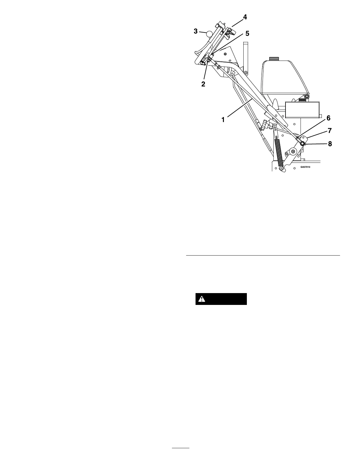
Figure6
RightHandSideofUnitShown
1.Driveleverlinkage
2.5/16-18inchnylocnut
3.Speedcontrolleverinneutral
4.Driveleversinneutral
5.5/16-18x13/4inchhexcapscrew
6.3/8-24inchLHjamnut
7.Hydrocontrolarmweldment
8.Lowerballjoint
AdjustingtheDriveLeverLinkages
1.Raisetherearofmachineoffoftheground.
CAUTION
Raisingtherearoftheunitforassemblyrelying
solelyonmechanicalorhydraulicjackscouldbe
dangerous.Themechanicalorhydraulicjacks
maynotbeenoughsupportormaymalfunction
allowingtheunittofall,whichcouldcause
injury.
DoNotrelysolelyonmechanicalorhydraulic
jacksforsupport.Useadequatejackstandsor
equivalentsupport.
2.Withtherearofmachineonjackstandsandengine
runningatfullthrottle,disengagetheparkbrake
andmovethespeedcontrollevertothemidway
position.Movetherespectivedriveleverupward
untilitreachestheneutralpositionandengagethe
neutrallocklatches(Figure7).Ifthetirerotatesin
4
 Loading...