Maintenance
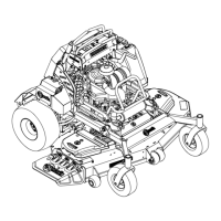
Figure18
1.Installbushinginbladepriortoinstallingbushingin
spindle.
B.Installbushing/bladeassemblyintospindle.
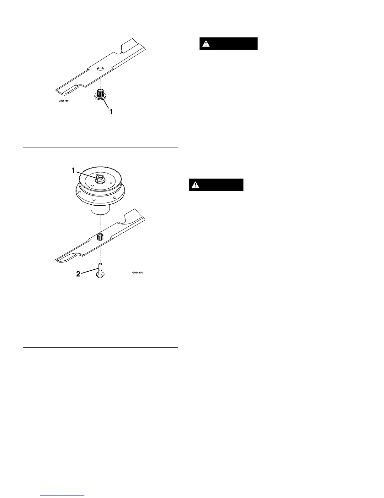
Figure19
1.Usewrenchherefor
bladeinstallation.This
nuthasbeentorquedto
130-160ft-lb(176–217
N-m)
2.T orqueto50-60ft-lb
(68-81N-m)Apply
lubricanttothreads
asneededtoprevent
seizing.Copper-based
anti-seizepreferable.
Greaseacceptable
substitute.
C.Applylubricanttothreadsofbladeboltas
neededtopreventseizing.Copper-based
anti-seizepreferable.Greaseacceptable
substitute.Installbladeboltngertight.Place
wrenchonthetopspindlenutthentorquethe
bladeboltsto50-60ft-lb(68-81N-m).
WARNING
Incorrectinstallationofthebladeor
componentsusedtoretainthebladecan
bedangerous.Failuretousealloriginal
componentsandassembledasshowncould
allowabladeorbladecomponenttobe
thrownoutfromunderthedeckresultingin
seriouspersonalinjuryordeath.
AlwaysinstalltheoriginalExmarkblades,
bladebushings,andbladeboltsasshown.
CheckSafetyInterlock
System
ServiceInterval:Beforeeachuseordaily
CAUTION
Ifsafetyinterlockswitchesaredisconnected
ordamagedthemachinecouldoperate
unexpectedlycausingpersonalinjury.
•Donottamperwiththeinterlockswitches.
•Checktheoperationoftheinterlockswitches
dailyandreplaceanydamagedswitches
beforeoperatingthemachine.
UnderstandingtheSafetyInterlockSystem
Thesafetyinterlocksystemisdesignedtopreventthe
mowerbladesfromrotatingunless:
•Therightsidemotioncontrolleverismovedto
thecenter,operatingposition.
•Thebladecontrolswitch(PTO)ispulledon.
Thesafetyinterlocksystemisdesignedtostop
themowerbladesifyoumoveorreleasetheright
sidemotioncontrolleverintothePTOdisengage
position.
•Therightsidemotioncontrolleverismovedto
thecenter,operatingposition,theparkingbrake
isengaged,andthebladecontrolswitch(PTO)is
pulledon.
CheckingtheSafetyInterlockSystem
1.Starttheengine.
2.Settheparkingbrake.
3.Movethemotioncontrolleversforward.
Theengineshouldinitiateshutdownafter
momentarypause.
4.Starttheengineandreleasetheparkingbrake.
30