341
4
6
5
3
2
1
2
4
6
5
3
2
1
a
b
c
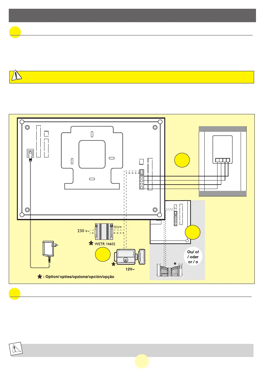
4. WIRING
Use the following wires: • lengths up to 30 metres: 4 x 6/10 wires + 2
• lengths between 30 and 100 metres: 4 x 1.5 mm
2
wires + 2
1. Connect the wires securely following the wiring diagram below.
2. To connect the video camera, 4 wires are needed for all the functions.
•Terminal “1” on the screen to terminal “1” of the video camera.
•Terminal “2” on the screen to terminal “2” of the video camera.
•Terminal “3” on the screen to terminal “3” of the video camera.
•Terminal “4” on the screen to terminal “4” of the video camera.
C
AUTION
:
UNDER NO CIRCUMSTANCES SHOULD THE WIRES BE DOUBLED TO MAKE THEM THICKER
a.
Connecting the videophone
The electrical strike or lock you will install will imperatively be equipped with a mechanical memory as every EXTEL
references
•
For wiring, refer to the label at the rear of the monitor and the camera
b. Connecting an electrical strike or lock.
When the installation includes a catch or an electric lock, provide two extra wires to connect the catch to the
monitor (see wiring p.12).
Connect it to terminals 5 and 6 on the back of the monitor.
Warning: the power supply for the catch or the electric lock is provided by an independent transformer which is
not supplied with the kit. (rExtel ref.: WETR 14602).
Note this function is only valid when the screen is switched on.
23GB
MANUAL WEVP 626 E BIS LANGU.qxd 28/09/07 16:01 Page 26