CHAPTER 27
PAGE 20
MAINTENANCE MANUAL EXTRA 300/SC
PAGE DATE: 1. August 2014
Figure 15 Pedal Adjustment Position
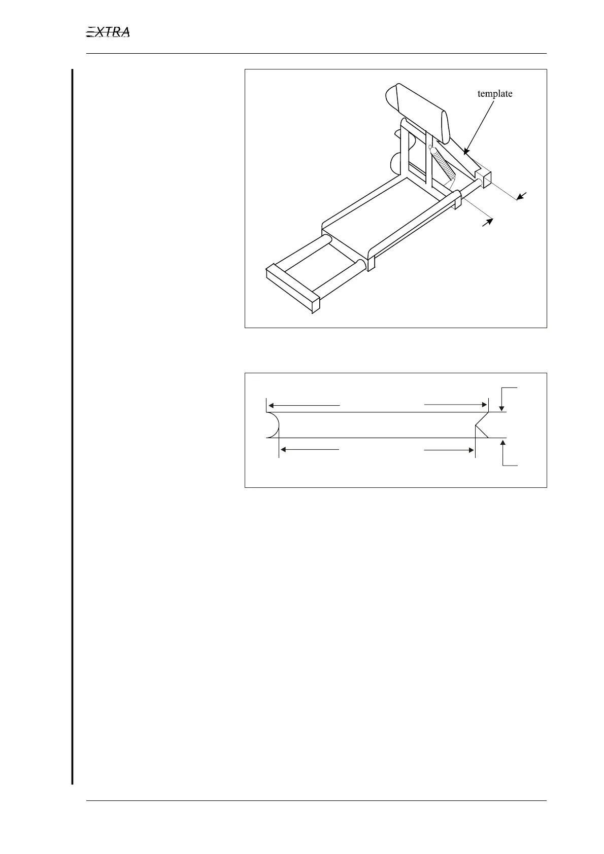
3 Fix pedals using templates as shown in Figure 16.
230 mm (9.06”)
205 mm (8.07”)
30 mm (1.18”)
Figure 16 Pedal Fix Template
4 Secure the rudder in 0°-position.
5 Check that the 550 mm PTFE protective hose is placed on
the pre-assembled control cable.
6 Mount the shackle of the pre-assembled control cable end
to the front cable attachment point. Install bolt LN 9037-
06028 (13, Figure 17), 4 x DIN 125-8.4 washers (7)(two
on both sides of the thimble (10)), 2 x DIN 125-6.3 wash-
ers (6), the bushing EA-33102.4 (11), and the LN 9348-06
nut (8).
7 Thread the cable including the protective PTFE hose through
"S"-shaped tube at the pedal, the fairleads and the hole in the
fabric to the tail. Let the front end of the protective PTFE
hose extend to 20 mm in front of the "S"-shaped tube.