CHAPTER 28
PAGE 27
MAINTENANCE MANUAL EXTRA 300/SC
PAGE DATE: 1. August 2014
MAINTENANCE PRACTICES
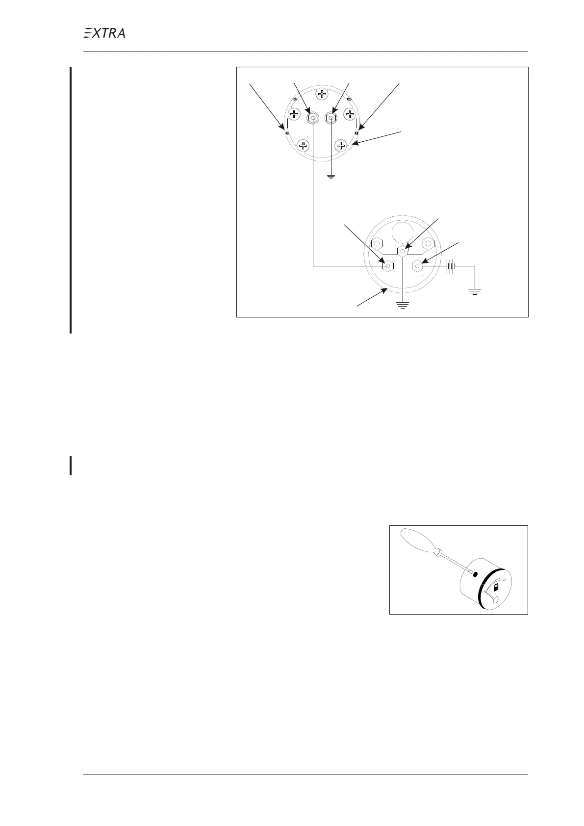
Ground Stud =
Ground Stud
“G”
Signal Stud
Signal Stud
“S” =
“I” = Ignition Voltage
(+12 VDC)
Tubular Tank Unit
Fuel Quantity Indicator
S
G
I
Figure 12 Wiring Diagram Datcom System
28-40-02 Fuel Quantity Indicator (Center Tanks)
Calibration (VDO system only)
1 Drain the fuel system (refer to Chapter 12-10-02).
2 Remove the fuel quantity indicator following step 2 of Chap-
ter 28-40-01.
3 Bring indicator to „0“-posi-
tion by turning the adjust-
ment screw.
4 Reinstall the fuel quantity indicator.