For a description of the LEDs and their operation, see ExtremeSwitching 210 and 220 Series Switch
LEDs on page 23.
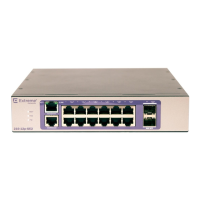
Figure 3: ExtremeSwitching 210-12p-GE2 Switch Front Panel
1 = Ethernet management port 3 = 10/100/1000BASE-T ports
2 = Console port 4 = SFP ports
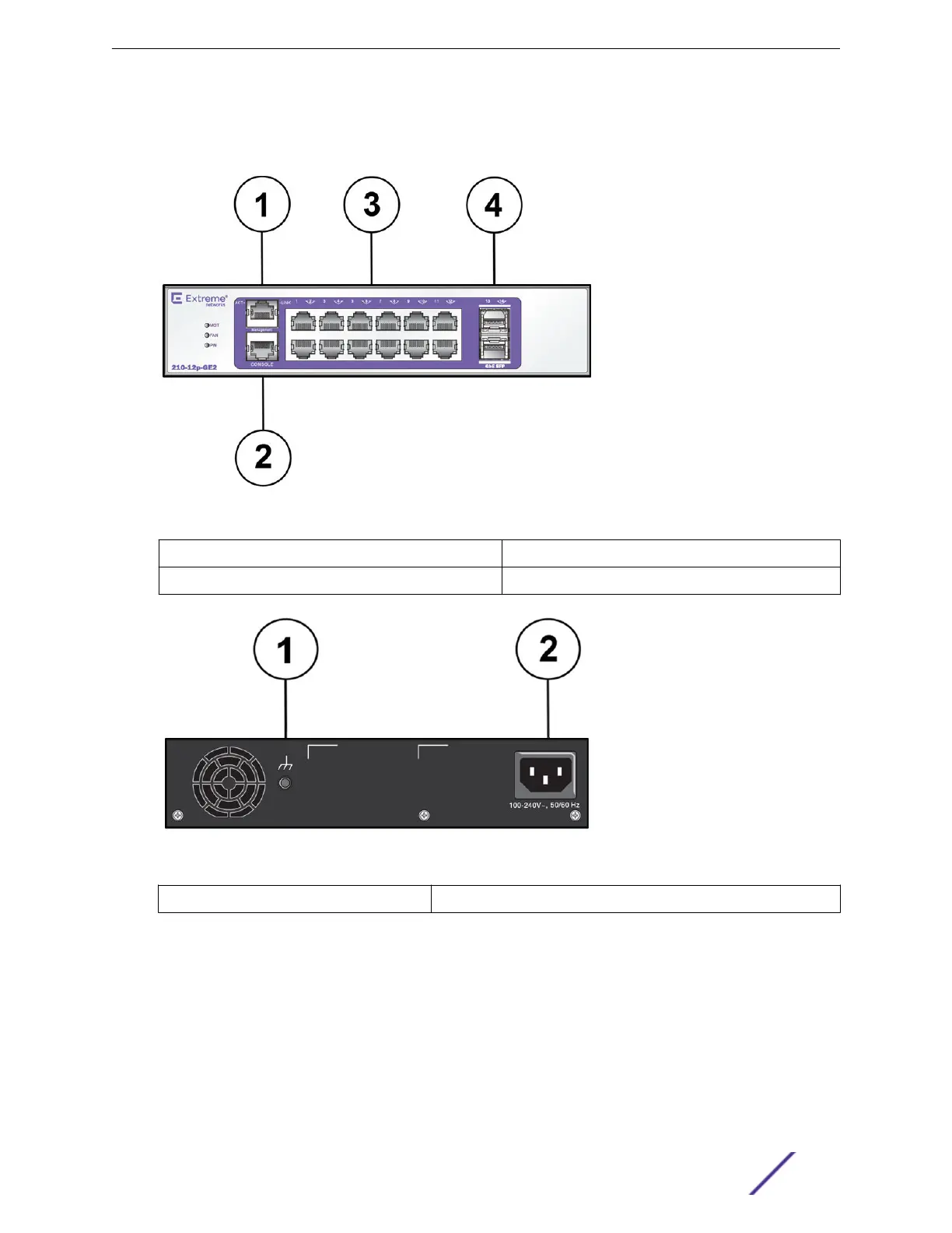
Figure 4: ExtremeSwitching 210-12p-GE2 Switch Rear Panel
1 = Grounding point
2 = AC power input connector
ExtremeSwitching 210-24t-GE2 Switch Ports and Slots
The ExtremeSwitching 210-24t-GE2 switch ports and slots include:
•
24 10/100/1000BASE-T ports (ports 1–24) that provide 1 GbE connectivity
•
Two dedicated 1 GbE SFP ports (ports 25–26)
•
Ethernet management port (10/100BASE-T)
ExtremeSwitching 210 and 220 Series Switches
ExtremeSwitching 210 and 220 Series Switches: Hardware Installation Guide 12
 Loading...

