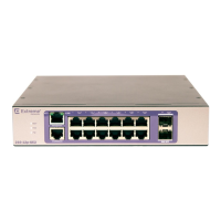
Figure 24: ExtremeSwitching 220-48p-10GE4 Switch Rear Panel
1 = Redundant power input 3 = AC power input connector
2 = Grounding point
ExtremeSwitching 210 and 220 Series Switch LEDs
The following table describes the meanings of the LEDs on the ExtremeSwitching 210 and 220 series
switches.
Table 3: Front Panel LEDs
Label or Type Color/State Meaning
MGT (Management) Slowly blinking green Power-on self test (POST) has finished. This is
normal operation.
Blinking green POST in progress.
O No power.
FAN Steady green Normal operation.
Blinking amber Failure.
O No power.
PW
(Power Supply)
Steady green Normal operation.
O No power.
RPS
(Remote Power Supply)
220 Series 24- and 48-port
models only
Steady green RPS working properly.
Blinking amber RPS failure.
O No RPS.
Pluggable Interfaces for ExtremeSwitching Switches
Some 210 and 220 series switches include ports that are compatible with a variety of optical modules,
including SFP and SFP+ modules. Extreme Networks optical modules are tested to work in all
supported Extreme Networks devices. We recommend that all customers use Extreme Networks optical
modules in their Extreme Networks devices.
Extreme Networks assumes no liability for third-party optical modules. Although Extreme Networks
does not block third-party optical modules, we cannot ensure that all third-party optical modules
ExtremeSwitching 210 and 220 Series Switches
ExtremeSwitching 210 and 220 Series Switches: Hardware Installation Guide 23
 Loading...

