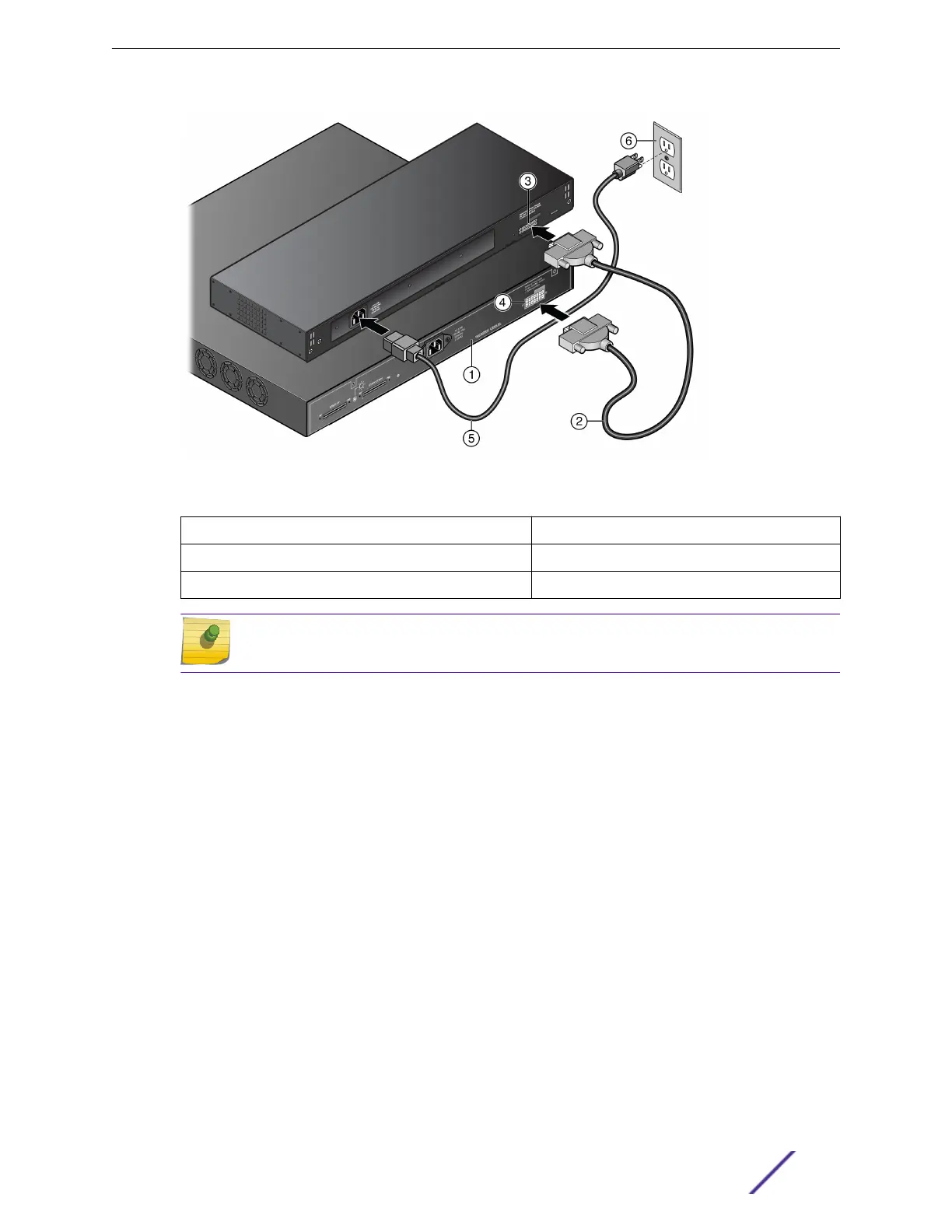
Figure 32: RPS Cable and AC Power Cord Connections for the RPS-500p
1 = PoE-compliant switch 4 = Redundant Power Supply connector on switch
2 = RPS cable 5 = AC power cord
3 = Redundant Power Supply connector on power supply 6 = AC power outlet with ground connection
Note
AC power cords and outlets vary depending on country.
3 Connect the AC power cord to the AC input power connector on the power supply.
4 Plug the AC power cord into the main AC power outlet.
The AC power LED on the front of the RPS-500p turns green to indicate that the connection was
successful and the power supply is operating properly.
If the LED does not light properly, follow these steps to troubleshoot:
•
Check the AC power cord connection at the AC power source and make sure the power source is
within specification.
•
Check the AC power connection to the power supply.
•
Swap the AC power cord with one that is known to work properly.
External Power Supplies
ExtremeSwitching 210 and 220 Series Switches: Hardware Installation Guide 35
 Loading...

