3 Remove the cover plate from the VIM5 slot (#2 Phillips screwdriver required).
a Remove the retaining screws at the top corners of the slot cover plate, and set the screws aside
in a safe place.
b Save the retaining screws to secure the new module in the switch.
c Pull the cover plate away from the module slot.
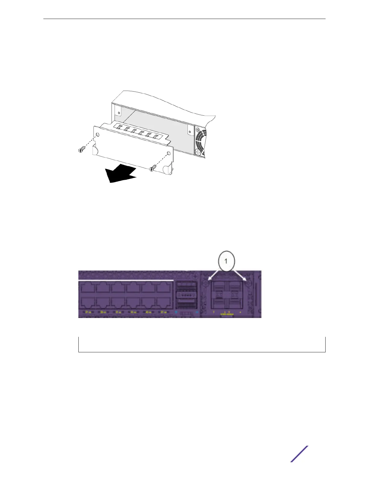
Figure 18: Removing a slot Cover Plate (VIM slot cover shown)
4 Remove the new VIM5 from its anti-static packaging.
5 Install the VIM5 in the switch:
a Carefully slide the VIM5 module into the switch.
b Insert and tighten the retaining screws you removed in step 3.a on page 47, using the screws
provided.
Figure 19: Tighten Screws on the Inserted VIM5 Module
1 = VIM5 module retaining screw locations
Installing Expansion Modules
VSP 4900 Series Switches: Hardware Installation Guide 47
 Loading...