IPCP Pro Series • Hardware Features and Installation 19
Additional Control Ports
H
Flex I/O ports —To allow the IPCPProSeries control processor to monitor devices to
trigger events, connect switches, sensors, LEDs, relays, or similar items to these ports,
which can be configured as analog inputs, or as digital inputs or outputs with or without
+5VDC pull-up. These ports can trigger events or functions (such as triggering relays,
issuing commands, or sending an e-mail) that have been configured using GC.
By default these ports are set to digital input mode with pullup disabled.
FLEX I/O
3214G
FLEX
I/O
34
21
Ground
Wire
Nut
Device 4
Device 3
Device 2
Device 1
Share the same ground among
ex I/O connections.
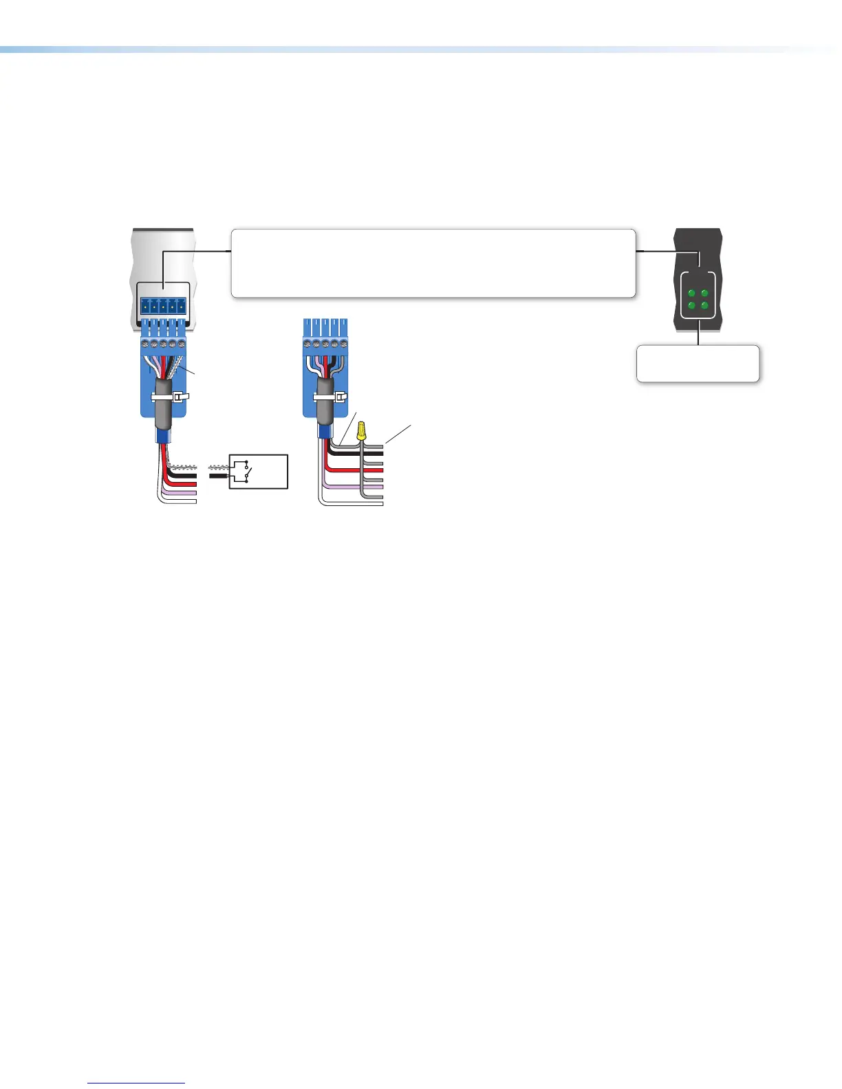
Flex I/O (digital input/output or analog input)
Congure each port as an analog input or as a digital input or output with or without +5 VDC pull-up.
Use these ports to:
• Monitor or trigger events and functions (toggle relays, issue commands, send e-mail), once congured.
• Power LEDs, incandescent lights, or other devices that accept a TTL signal.
(Switches, sensors,
LEDs, relays, or
similar items)
Switch,
Sensor
2
3
4
G
Heat
Shrink
Over
Shield
Wires
Flex I/O LEDs
Light when the corresponding
ports are active.
Rear Panel Front Panel
Figure 15. Flex I/O Port Wiring Examples
Analog input — When a Flex I/O port is configured as an analog input, the port can
measure 0 to 25.3 VDC with 12-bit accuracy. A DC level is indicated by a count from
0-4096 (≈ 6 mV per count).
Digital input — To allow the IPCP to monitor external devices that do not use RS-232
communication, connect a switch, motion sensor, moisture sensor, tally feedback
output, button pad, or a similar item to a Flex I/O port and configure it for digital input.
When configured as a digital input, the port is set to measure two states: high and low.
The port accepts 0 to 25.3 VDC input.
For flex I/O ports, threshold voltages are adjustable. Default thresholds are:
• 0.8VDC — port on, logic low
• 2.4VDC — port off, logic high
There is also an internal, selectable, pull-up resistor connected to +5VDC.
Digital output — To power LEDs, incandescent lights, or other devices that accept a
TTL signal, or to provide contact closure control for projector lifts, motorized screens,
room or light switches via an Extron IPA T RLY4 or similar device, you can use one or
more of these ports as a digital output. When a port is configured for digital output, it
offers two output states: on and off.
• When the port is set to an “on” state, (the circuit is closed), the I/O pin is connected
to ground. Output voltage is less than 0.5volts.
• When the port is set to the “off” state (the circuit is open), the output pin is not
connected. If the application calls for TTL compatibility, the digital output circuit can
be set up to provide a 2kohm pull-up resistor to +5VDC.
• If the pull-up resistor is disabled, voltage output is determined by an external
source device.
• If the pull-up resistor is enabled, voltage output is 4.3VDC.
Each I/O port is capable of accepting 250mA, maximum.