Installation and
Operation
This section provides the following details:
• Connection Guidelines
• Rear Panel Connections
• Cabling and Setup
• Front Panel Features
• System Operation
• Troubleshooting
Connection Guidelines
The USB Extender Plus can be installed in existing and new systems within the following
guidelines:
• The USB Extender Plus cannot be cascaded (you cannot sequentially connect a
USB Extender Plus to another USB Extender Plus or to a FOX T/R USB Extender Plus).
• The extenders have three internal hubs, two of which can be disabled via SIS or the
Product Configuration Software (PCS). The hubs that can be disabled are those for
peripheral emulation and 1:N network pairing.
• The USB Extender Plus is able to support a maximum of 31 downstream USB devices
(including hubs). For example, if two four-port USB hubs are connected to a receiver,
that totals ten devices (two hub connections plus the eight hub ports).
• When extenders are configured for 1:N (multiple) network pairing, a transmitter can
support only one high speed device at a time. For point-to-point pairing, the transmitter
can support multiple high speed devices.
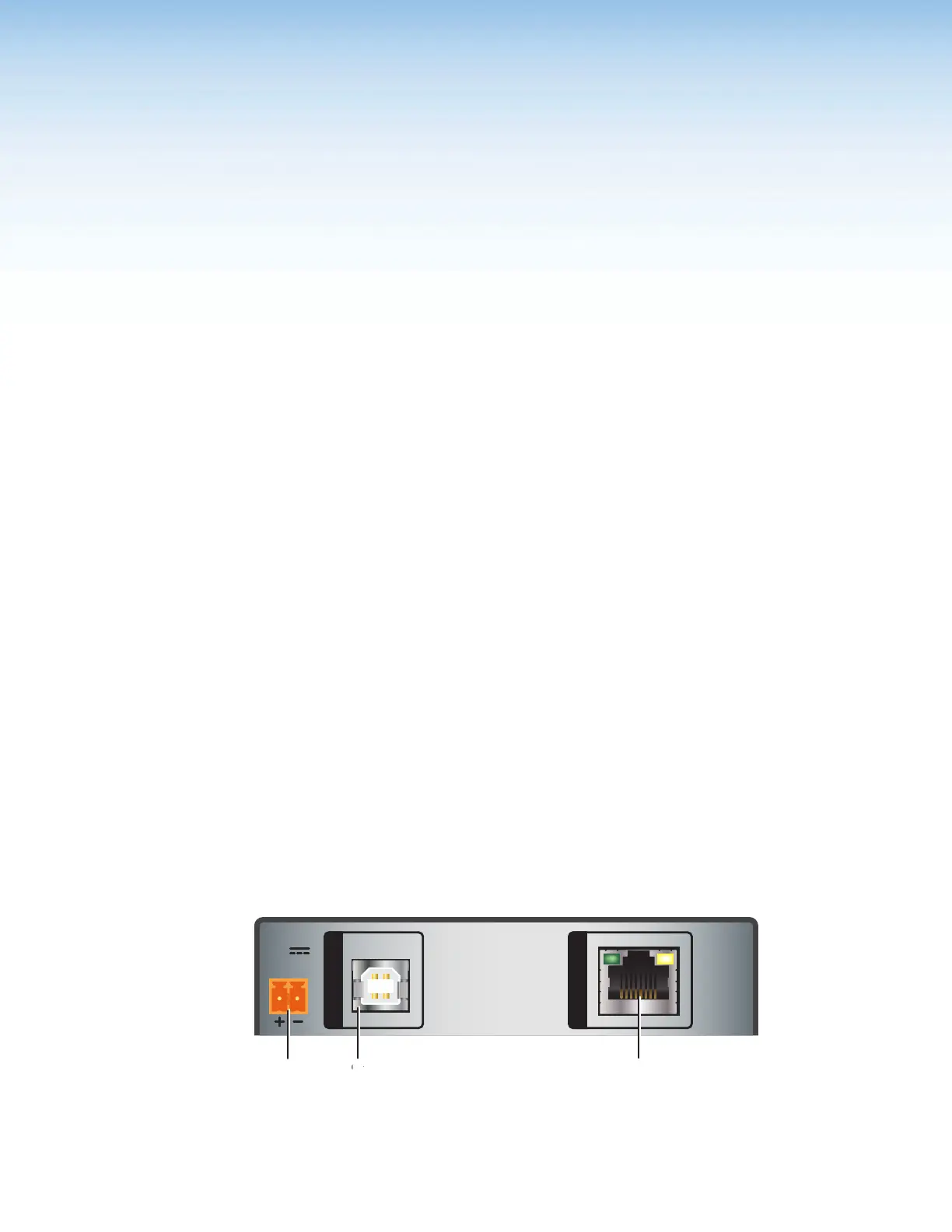
Rear Panel Connections
Transmitter Rear Panels — USB Extender Plus T, Standard and HID-only
HOST
POWER
12V
1.0 A MAX
INPUT
OUTPUT
A
Power connector
C
Twisted Pair Output Connector
B
Host (Input) connector
Figure 4. Transmitter Rear Panel Connectors (Rack Mountable Models)
USB Extender Plus Series • Installation and Operation
5