Receiver Rear Panels — USB Extender Plus R, Standard and HID-only
1
2
3
4
POWER
12V
1.0A MAX
INPUT
OUTPUTS
A
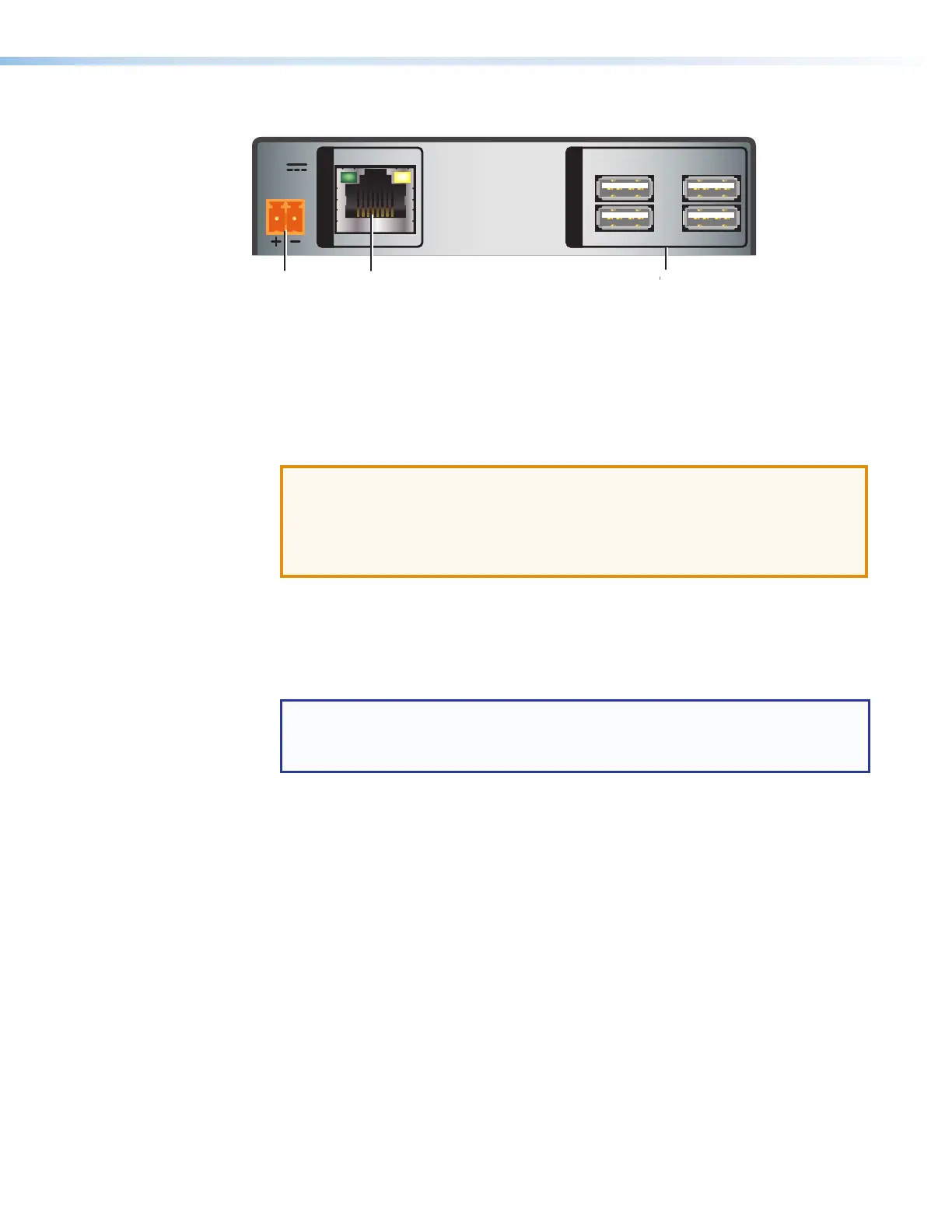
Power connector
C
Twisted Pair Input connector
D
USB hub connectors
Figure 5. Receiver Rear Panel Connectors (Rack Mountable Models)
A
Power connector — Connect a provided 12 VDC, 1 A max. external power supply to
this 2-pole, 3.5mm captive screw connector.
ATTENTION:
• Before connecting power, be sure to read the Power Supply Attention
Notices on page 9.
• Ne branchez pas de sources d’alimentation externes avant d’avoir lu les mises
en garde sur la page 9.
B
Host (input) connector — Connect a USB type A to B cable between this USB type
B port and the USB port of a host. The USBExtender Plus is USB3.0 compliant and
supports data transfers of 480 Mbps (high speed), 12Mbps (full speed), and 1.5Mbps
(low speed).
C
Twisted pair connector —
NOTES:
• On the transmitters, the RJ-45 connector is the output port.
• On the receivers, the RJ-45 connector is the input port.
• Transmitter — Connect a TP cable from the RJ-45 Input connector of the receiver
(see figure 5,
C
) to this female RJ-45 connector.
• Receiver — Connect a TP cable from the RJ-45 Output connector of the
transmitter to this connector.
See Twisted Pair Cable Termination on page 37 to wire the RJ-45 connectors if
necessary.
D
USB Hub connectors — The built-in four port hub has four female USB Type A
connectors. The connections are USB 3.0 compatible, providing +5VDC at up to
500mA to connected USB peripherals requiring power.
USB Extender Plus Series • Installation and Operation 6