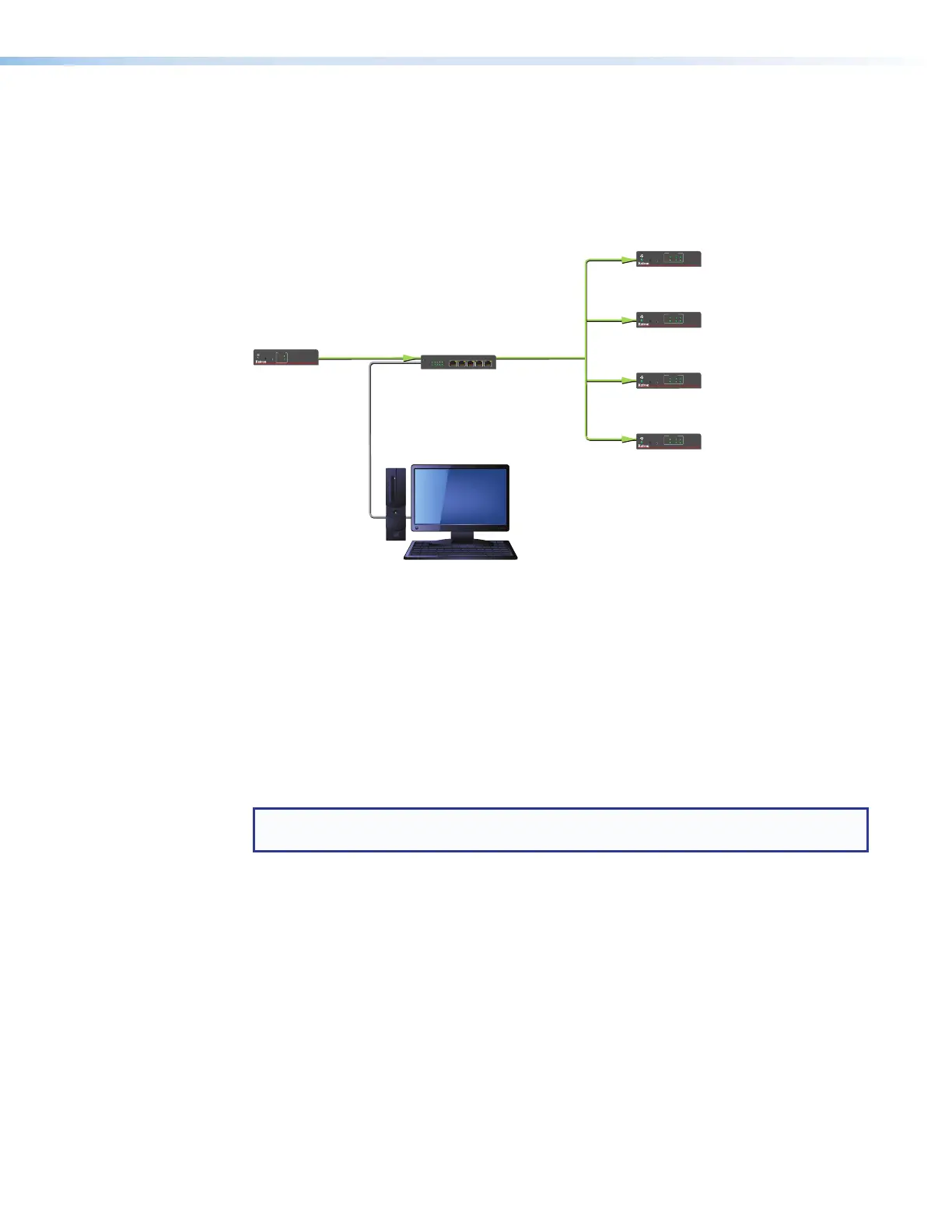
Pairing a Transmitter to Multiple Receivers
You can also connect a transmitter and up to four receivers to a network switch, then tie
(pair) the transmitter to the connected receivers using the Extron PCS Control Program. The
computer communicates with all connected USB Extenders via the network and makes ties
through their hardware (MAC) addresses (see the example in figure 14).
Gigabit Network Switch
Rx 4
USB EXTENDER Plus R
CONFIG
PAIR
STATUS
LINK
HOST
1
3
2
4
Rx 3
USB EXTENDER Plus R
CONFIG
PAIR
STATUS
LINK
HOST
1
3
2
4
Rx 2
USB EXTENDER Plus R
CONFIG
PAIR
STATUS
LINK
HOST
1
3
2
4
Rx 1
USB EXTENDER Plus R
CONFIG
PAIR
STATUS
LINK
HOST
1
3
2
4
USB EXTENDER Plus T
STATUS
LINK
HOST
CONFIG
PAIR
LINK
HOST
PC
(running PCS 3.3 or higher
Figure 14. Tying a Transmitter to Four Receivers using a Network Connection
See Using the Configuration Software on page 27 to download the program and use it
to tie the transmitter to the receivers.
Enabling and Disabling Peripheral Emulation
The transmitter can be set up to emulate a mouse and keyboard to the host computer that
is connected to the transmitter Host input port. This allows the computer to boot up in the
event that it requires a USB keyboard or mouse to be present.
NOTE: A USB extender with peripheral emulation enabled has three hubs internally (two
hubs with peripheral emulation disabled). Additional hubs may be on the host PC.
Using SIS commands, you can disable and enable peripheral emulation. By default,
peripheral emulation is enabled. The following peripheral emulation commands can be
issued to the transmitter only:
• To disable:
E
E 0 USBC
}
• To enable:
E
E 1 USBC
}
See Remote Configuration and Control, beginning on page 22, for information on
entering SIS commands.
USB Extender Plus Series • Installation and Operation 16