XTP II CrossPoint Series • Installation4
Installation
This section describes installation of the XTP II CrossPoint matrix
switchers, including connections and features. Topics that are
covered include:
• Rear Panel
• Front Panel
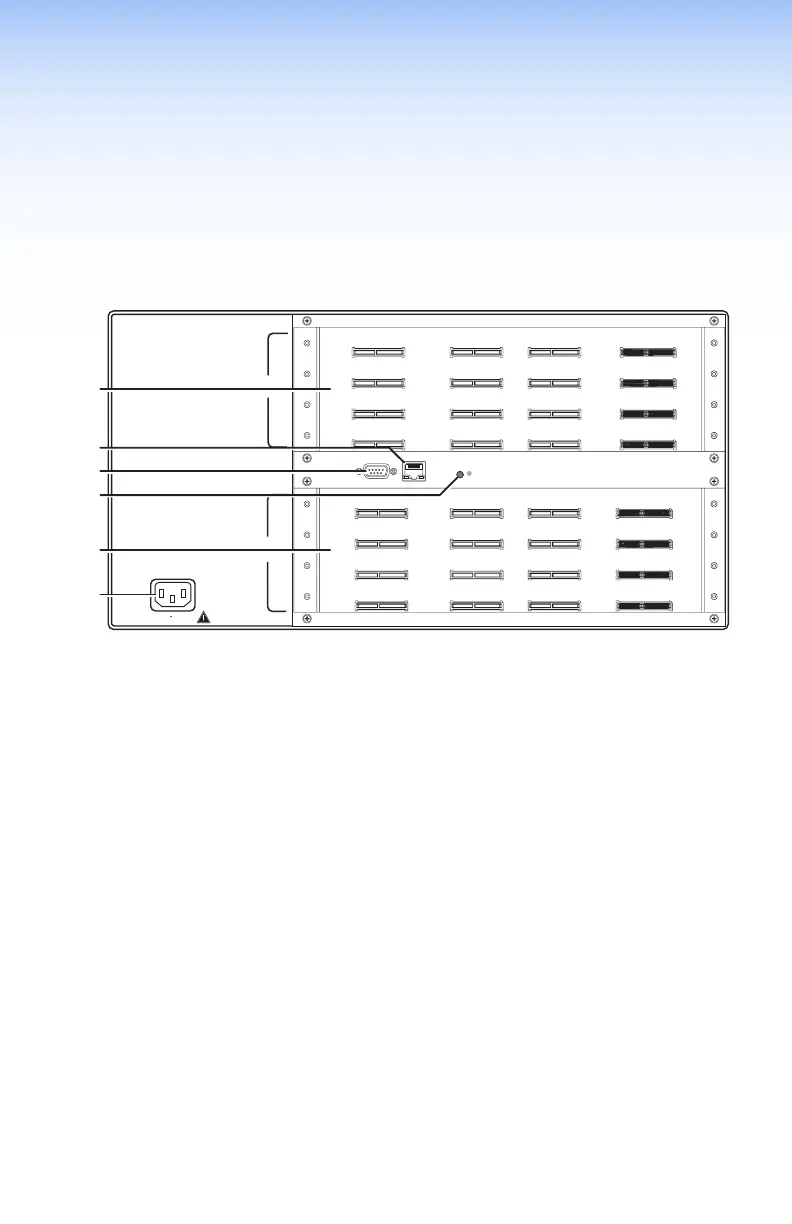
Rear Panel
INPUTS
OUTPUTS
100-240V
50-60Hz
-- A MAX
1−4
5−8
9−12
13−16
1−4
5−8
9−12
13−16
LAN
ACTLINK
REMOTE
RS-232/RS-422
RESET
Figure 2. XTP II CrossPoint 1600 Matrix Switcher Rear Panel
A
Input boards (see next page)
B
Output boards (see page 9)
C
LAN port (see page 12)
D
Remote port (see page 12)
E
Reset button (see page 12)
F
Power connector (see page 12)
G
Power connector (see page 12)
I/O Board Configuration Overview
See gure 2, figure 3 on the next page, and figure 4 on page 6.
Input boards are installed in one or two blocks or spaces and output
boards are installed in separate spaces. Each board position is
identied by the input or output numbers supported by the position
(1-2, 5-8, and so on).
On the XTP II CrossPoint 1600, boards are installed horizontally,
input boards in the top space and output boards in the bottom
space. Inputs or output positions are 1-4 on the top space and
13-16 on the bottom space.
On the XTP II CrossPoint 3200 and the XTP II CrossPoint 6400,
boards are installed vertically; input boards on the left and output
boards on the right. Input or output positions are 1-4 in the left
space and 29-32 in the right space. For the XTP II CrossPoint 6400,
input and outputs 33-64 are in the second blocks of boards.

 Loading...


