5XTP II CrossPoint Series • Installation
Installation
This section describes installation of the XTP II CrossPoint matrix
switchers, including connections and features. Topics that are
covered include:
• Rear Panel
• Front Panel
Rear Panel
INPUTS
OUTPUTS
100-240V
50-60Hz
-- A MAX
1−4
5−8
9−12
13−16
1−4
5−8
9−12
13−16
LAN
ACTLINK
REMOTE
RS-232/RS-422
RESET
AA
BB
CC
DD
EE
FF
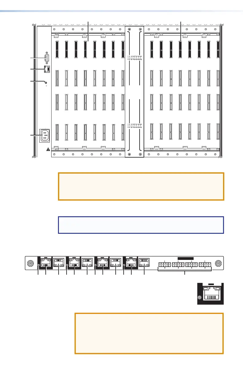
Figure 2. XTP II CrossPoint 1600 Matrix Switcher Rear Panel
A
Input boards (see next page)
B
Output boards (see page 9)
C
LAN port (see page 12)
D
Remote port (see page 12)
E
Reset button (see page 12)
F
Power connector (see page 12)
G
Power connector (see page 12)
I/O Board Configuration Overview
See gure 2, figure 3 on the next page, and figure 4 on page 6.
Input boards are installed in one or two blocks or spaces and output
boards are installed in separate spaces. Each board position is
identied by the input or output numbers supported by the position
(1-2, 5-8, and so on).
On the XTP II CrossPoint 1600, boards are installed horizontally,
input boards in the top space and output boards in the bottom
space. Inputs or output positions are 1-4 on the top space and
13-16 on the bottom space.
On the XTP II CrossPoint 3200 and the XTP II CrossPoint 6400,
boards are installed vertically; input boards on the left and output
boards on the right. Input or output positions are 1-4 in the left
space and 29-32 in the right space. For the XTP II CrossPoint 6400,
input and outputs 33-64 are in the second blocks of boards.
LAN
ACT
LINK
RESET
100-240V
50-60Hz
--A MAX
REMOTE
RS 232/RS422
DISCONNECT POWER
CORD BEFORE
SERVICING
I
N
P
U
T
S
O
U
T
P
U
T
S
A
B
Figure 3. XTP II CrossPoint 3200 Matrix Switcher Rear Panel
ATTENTION:
• Unplug the product and other devices before proceeding.
• Débranchez le produit et les autres appareils avant de procéder.
Inputs and Outputs
NOTE: See item
A
on figure 2 on the previous page, figure 3
above, and figure 4 on page 6.
A
Input boards space — Install input boards.
XTP CP 4i and XTP CP 4i 4K (XTP input board)
IN
XTP CP 4i
RS-232 IR
Tx Rx Tx Rx
RS-232 IR
Tx Rx Tx Rx
RS-232 IR
Tx Rx Tx Rx
RS-232 IR
Tx Rx Tx Rx
SIG LINK
XTP
PWR
LAN
XTP
PWR
LAN
XTP
PWR
LAN
XTP
PWR
LAN
IR/RS-232 OVER XTP
SIG LINK SIG LINK SIG LINK
11111111333333332244222222
1
XTP input connectors — Connect a TP cable
between an Extron XTP transmitter and this
connector (see TP connectors on page 13 to
wire the connectors).
ATTENTION:
• Do not connect these ports to a computer data or
telecommunications network.
• Ne connectez pas ces ports à des données
informatiques ou à un réseau de télécommunications.
PWR

 Loading...


