10 XTP II CrossPoint Series • Installation
NOTE: See item
B
on figure 2 on page 4, figure 3 on
page 5, and figure 4 on page 6.
2
XTP power indicators — Indicate the status of the PoX
provided to the endpoint as follows:
Lit green — The board is providing XTP power to the
endpoint.
Lit amber — XTP power is available, but disabled.
Blinking amber — A wiring fault exists.
Unlit — The endpoint cannot receive power over XTP.
3
LAN connectors — As desired, connect a TP cable
between a host device or control LAN and this
connector for passive extension to the LAN
(Ethernet) connector on the connected endpoint (see
TP connectors on page 13 to wire the connector).
4
RS-232/IR Over XTP connectors — If desired,
connect serial RS-232 signals, modulated IR
signals, or both to these 3.5 mm, 5-pole captive
screw connectors for bidirectional RS-232 and IR
communications on the associated inputs (see RS-232 and
IR connectors on page 15 to wire the connectors).
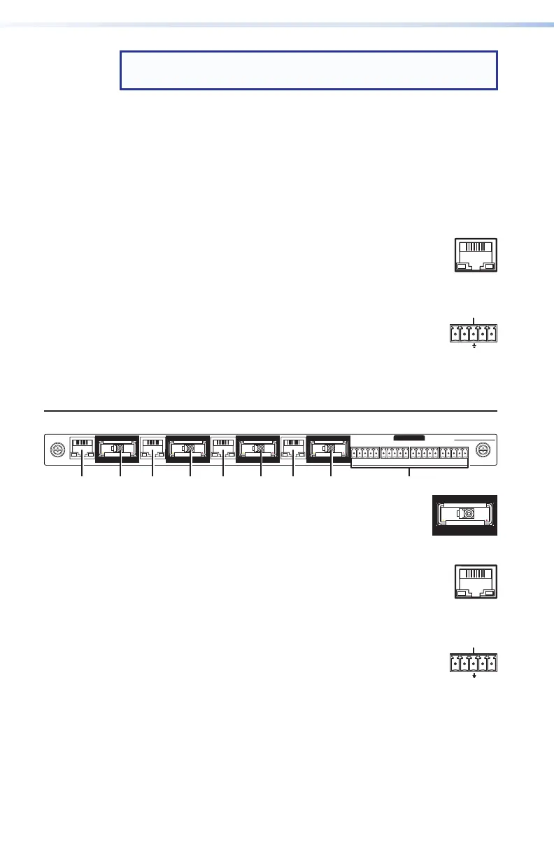
XTP CP 4o Fiber 4K (ber optic output board)
SIGLINK
XTP OUT
LANLAN LANLAN
SIGLINK
XTP OUT
SIGLINK
XTP OUT
SIGLINK
XTP OUT
OVER FIBER
XTP CP 4o FIBER 4K
RS-232
IR
Tx Rx GTxRx
RS-232
IR
Tx Rx GTxRx
RS-232
IR
Tx Rx GTxRx
RS-232
IR
Tx Rx GTxRx
5
XTP Out connectors — Connect up to four
fiber optic cable between these ports and the
Tx port of a compatible Extron fiber optic
receiver.
3
LAN connectors — As desired, connect a TP cable
between a host device or control LAN and this
connector for passive extension to the LAN
(Ethernet) connector on the connected endpoint (see
TP connectors on page 13 to wire the connector).
4
RS-232/IR Over XTP connectors — If desired,
connect serial RS-232 signals, modulated IR
signals, or both to these 3.5 mm, 5-pole captive
screw connectors for bidirectional RS-232 and IR
communications on the associated inputs (see RS-232 and
IR connectors on page 15 to wire the connectors).
SI
INK

 Loading...


