5.
INSTALLING MOUNTING BRACKET AND CONTROL BOX
5.1 The battery and control box ship from the factory attached to the mounting bracket and both will need to
be removed prior to installing the mounting bracket.
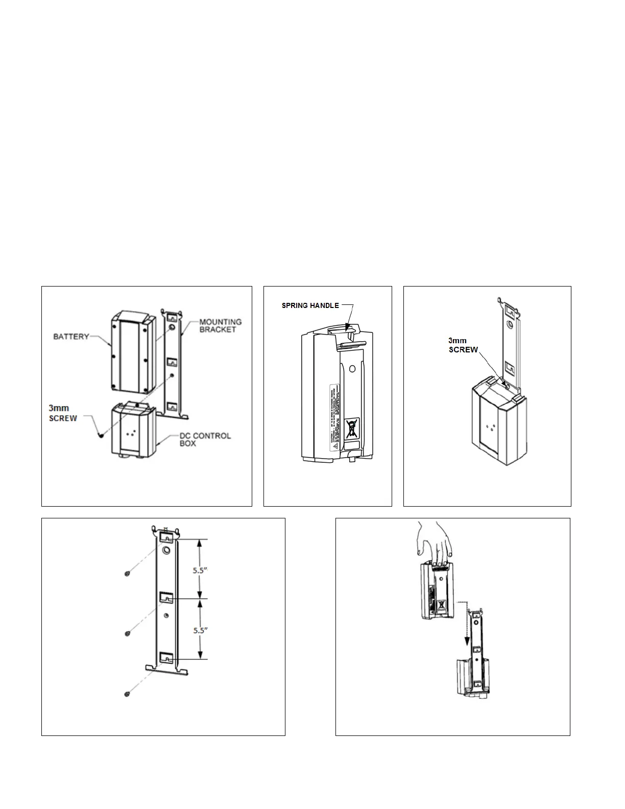
5.1.1 For component understanding, FIG. 16 illustrates the exploded view of the battery, control box,
and mounting bracket assembly.
5.2 Remove battery by squeezing the spring handle (FIG. 17) inward and pulling upward on the battery until
it slides up and disengages from the mounting bracket.
5.3 Remove control box from mounting bracket (FIG. 18) using 3mm hex key. Set screw aside for later use.
5.4 Choose a mounting location within 3’ of the toilet (the control box cord length requires installing the
mounting bracket within that range).
5.5 Install mounting bracket (hardware not included) to a wall or other suitable structure as chosen by
installer or contractor, using the on-center mounting pattern (FIG. 19).
5.6 Once the mounting bracket is installed, re-install control box by sliding control box onto mounting
bracket, ensuring that the slots on the back of the control box slide into the tabs on the mounting
bracket.
5.6.1 Secure control box to mounting bracket using 3mm hex key to re-insert the screw (FIG. 18).
5.7 Re-install battery by sliding battery onto mounting bracket. Battery is in place when it rests on top of the
control box and you hear the spring handle ‘click’ into place (FIG. 20).