TITAN
™
Code Compliant Modular Access System Installation Manual
6.7. FINAL CHECKS
6.7.1. Ensure that all fasteners are in place and secure.
6.7.2. Remove any installation debris and metal chips.
6.7.3. Ensure that the level and slope has not shifted during installation.
6.7.4. Ensure that all handrail ends are terminated with loops or returned to a post, the
ground, or building.
6.7.5. Check that all frame top rails are covered with end plugs and ramp side rails have
corner protector caps installed.
6.7.6. Walk on the assembled system and check for any undue movement. If movement is
noted, refer back to this Manual and ensure all installation steps were followed.
7. OPTIONAL EQUIPMENT
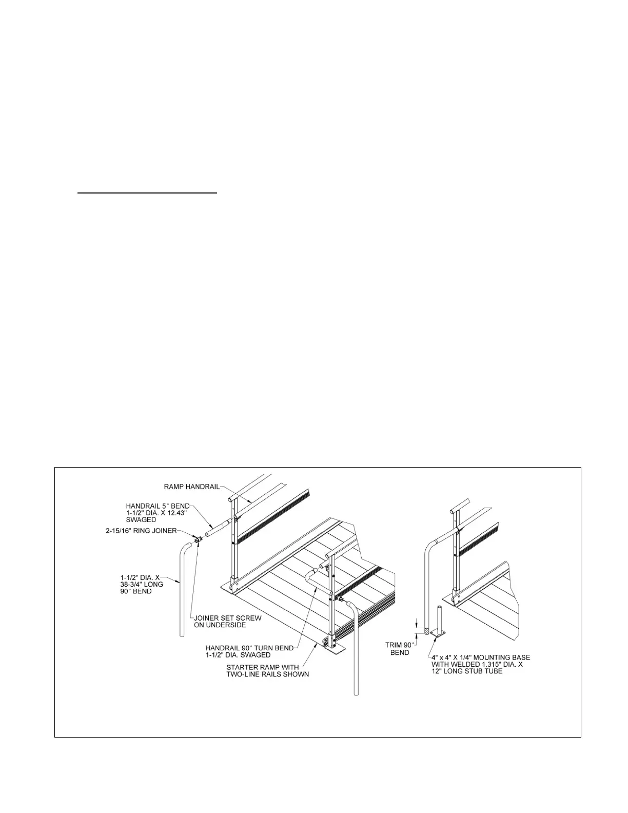
7.1. HANDRAIL RETURN TO GROUND
7.1.1. The handrail return to ground is most commonly used at the starter ramp but can also
be used to return a ramp handrail to the deck of a platform or an existing landing.
There are two options available: One extends the handrail one-foot level (minimum)
straight out from the end of a ramp or ramp run, the other makes a 90° turn then
extends one-foot level (minimum). Both can be used at either the top or bottom of a
ramp or ramp run and can be used on either side of the ramp.
7.1.2. Similar to the end loop (refer to ‘INSTALL RAMP HANDRAIL END LOOPS’ section), insert
the swaged end of the handrail 5
o
bend 1.5” diameter x 12.43” (swaged 5
o
bend) into
the end of a ramp handrail. Use a swaged 5° bend if installing a straight handrail
return to ground, use the handrail 90° turn bend 1.5” diameter swaged (swaged 90
0
bend) if installing a turn handrail return to ground (FIG. 7.1).
7.1.3. Insert a 2-15/16” ring joiner with the set screw on the underside of handrail (FIG. 7.1), and
then install the 4-1/4” leg of 1-1/2” diameter x 38-3/4” (non-swaged) 90
0
bend onto the
opposite end of the ring joiner with the 38-3/4” leg oriented toward the ground.
7.1.4. Hold the swaged 1-1/2” diameter tube bend, either the swaged 5
o
or swaged 90
0
bend, level to ground then trim the bottom of the 38-3/4” long, 90
0
bend such that
the bottom is above the weld which attaches the 1.315” x 12” long stub tube to the
4” x 4” x 1/4” mounting base (FIG. 7.1).