BEISSBARTH MT 740/ 745, 741/ 746
4-2
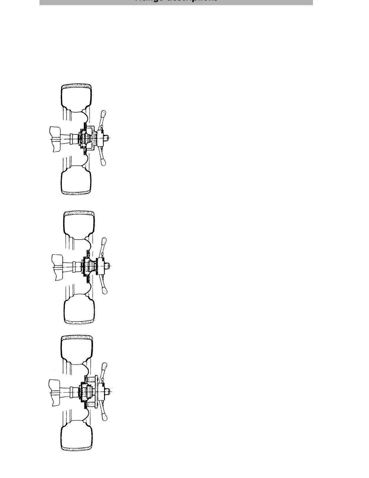
Hub centring flange
To clamp the wheels on to the balancing machine, use the hub-centring flange for all open-centred
wheels: these account for 80 % of all wheels.
To minimise clamping errors, the tyre valve should face downward when clamping the wheel on to
the flange and fitting to the vehicle.
1. Centring of the wheel with centring cones from the rim back,
and wheel mounting with clamping cap and quick-clamping
ring nut from the rim front:
Push coil spring over flange shaft.
Choose appropriate centring cone (cone must enter the hub
centre of the rim) and push cone against coil spring.
Hold the car wheel carefully against the centring cone and at
the same time press clamping cap over flange shaft against
rim.
Tighten wheel by hand at quick-clamping ring nut (see Figure 1).
Do not use tools such as a hammer.
2. Centring of wheel with centring cones from the rim back, and
mounting with pressure ring and quick-clamping ring nut from
the rim front:
Centring of the wheel is carried out as described in Item 1.
To fasten, use a pressure ring instead of a clamping cap.
This is a suitable method to centre light-alloy wheels with a
very high rim dome where the clamping cap does not reach
the mounting surface or if the rim (because of reinforcing ribs)
is of irregular shape (see Figure 2).
3. Centring of wheel with centring cones from the rim back, and
mounting with centring discs and quick-fastening ring nut from
the rim front:
Centring from the rim back is as described in Item 1.
To fasten, use a centring disc for the specific car type instead of
a clamping cap.
The centring disc's fixed bolts engage in the relevant rim
locating holes and press the wheel on to the flange mounting
surface via the quick-clamping ring nut (see Figure 3).
Fig. 1
Fig. 2
Fig. 3
Flange descriptions