Mt740/745, 741/746/En/Rev. 002/12/97 * 901.742 002
BEISSBARTH MT 740/ 745, 741/ 746
A-1
APPENDIX
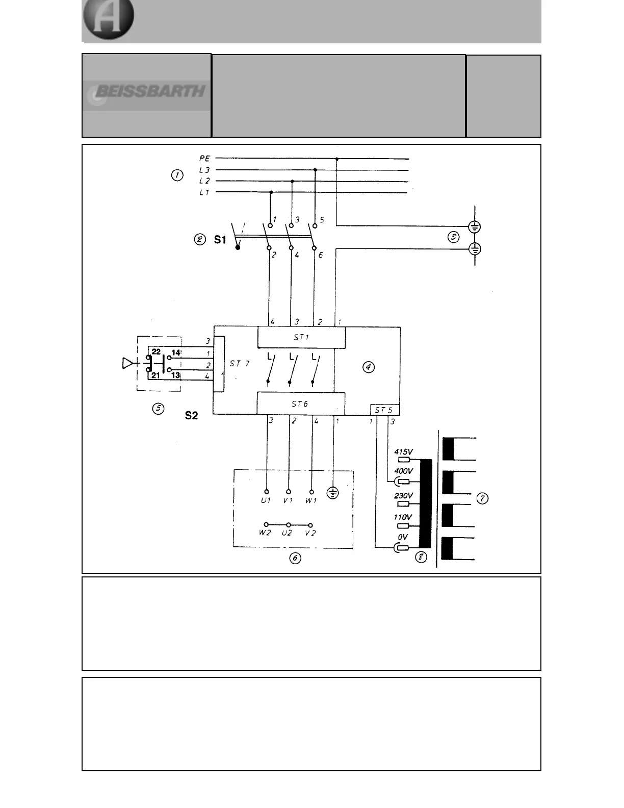
1. 3-phase mains supply
2. Master switch
3. Ground (earth) bar
4. Motor control board
5. Switch for safety hood (closed)
6. Motor terminal board
7. Power supply unit and electronics
8. Transformer
Circuit diagram for
MT 740/ 745
MT 741/ 746
3ph 220-240 V/ 380-420 V/ 50-60 Hz
Three-phase current version
EDV-Nr.
941 742 001
a. Machine is factory-preset to 3-phase, 400 V.
b. In start function the shaft rotates clockwise.
c. At the power stage the power circuit to the mains transformer is to be plugg e d
in according to the supply voltage.
d. For 3-phase 230 V supply, switch to motor to
∆∆
(delta), for 3-phase 400 V or 415 V to
star.
e. If direction of rotation is incorrect, exchange 2 phases at main supply.