BEISSBARTH MT 740/ 745, 741/ 746
A-2
EDV No.
941 741 002
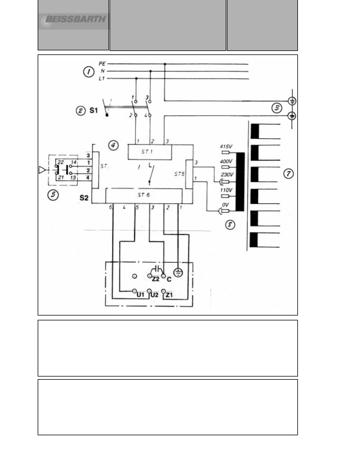
Circuit diagram for
MT 740/ 745
MT 741/ 746
1 ph 230 V/ 50-60 Hz
Single-phase current version
1. 1-phase mains supply
2. Master switch
3. Ground (earth) bar
4. Motor control board
5. Switch for safety hood (closed)
6. Power supply unit and electronics
7. transformer
a) Machine is factory-preset to single phase 230 V.
b) In start function the shaft rotates clockwise.
c) At the power stage, the power circuit to the mains transformer is to be plugged in
according to the supply voltage.
d) The motor’s direction of rotation can be changed by interchanging connections 2 and
3 at the plug 6 (ST6) on the motor control board. ( Make sure first that the motor
condenser is discharged).