Section:Chapter: 3
Page
JOG MODE2
JOGGING THE AXES
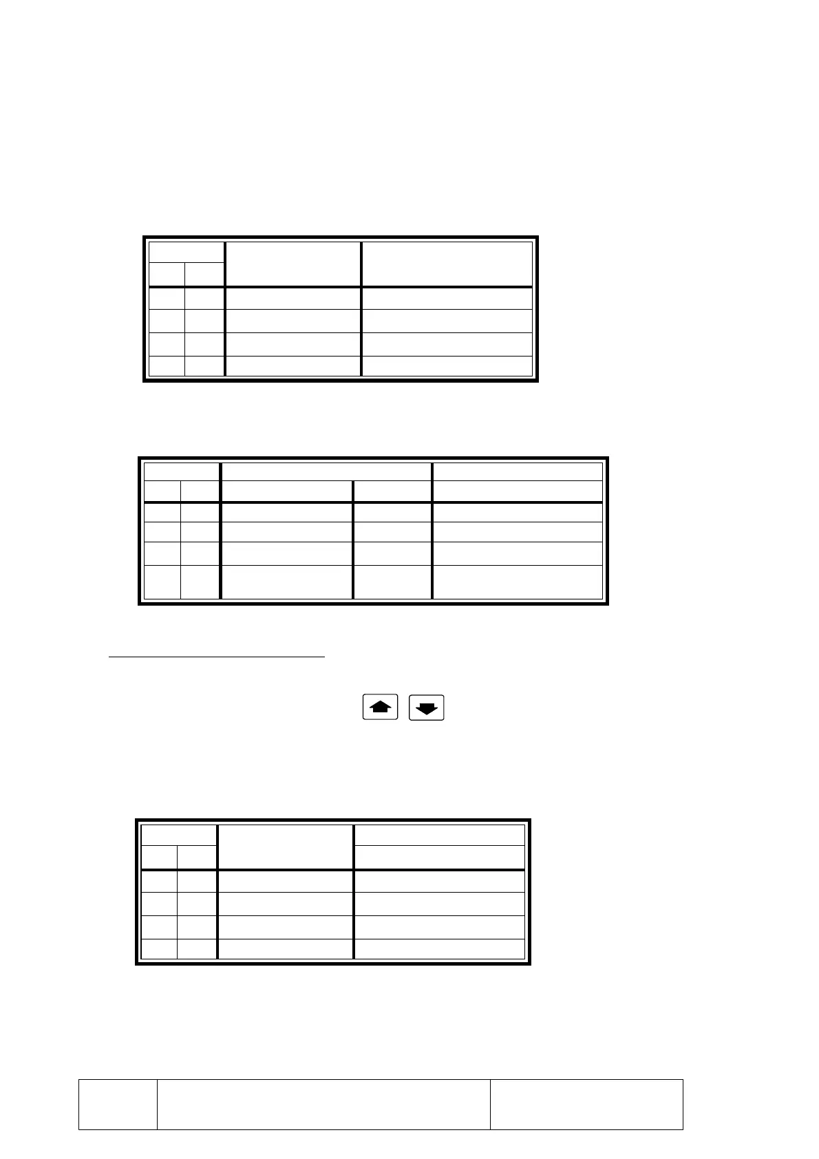
Pin
JOG type Moving distance
24 15
0 0 Continuous
0 1 Incremental 0.001 mm or 0.0001"
1 0 Incremental 0.010 mm or 0.0010"
1 1 Incremental 0.100 mm or 0.0100"
Pin Servocontrolled axes Non-servocontrolled axes
10 11 (G01/G02/G03) (G00) Range
1 1 25% 25% Slow range
1 0 50% 50% Ignored
0 0 100% 100% Ignored
0 1
If "P101(8)=0" 200%
If "P101(8)=1" 0%
100% Slow range
Pin
Multiplying Factor
Example: 250 lines/turn
24 15 Distance per turn
0 0 x 1 0.250 mm or 0.0250"
0 1 x 10 2.500 mm or 0.2500"
1 0 x 50 12.50 mm or 1.2500"
1 1 x 100 25.00 mm or 2.500"
When using the "JOG/handwheel 1 and 2" inputs of connector I/O2, the movements
will be either continuous or incremental and the axis will move the set distance every
time its jog key is pressed.
The table below shows the available options:
Activated pin = 1
Deactivated pin = 0
Furthermore, pins 10 and 11 of connector I/O1 allow the axis feedrate to be altered as
shown below.
Activated pin = 1, deactivated pin = 0
CNC with electronic handwheel
The positioning of axis X can either be carried out with the electronic handwheel or
from the keyboard, by using keys
Pins 15 and 24 of connector I/O2 display the multiplying factor applied by the CNC to
the pulses of the electronic handwheel.
This way, the actual axis jogging units result from multiplying the number of handwheel
pulses by this factor.
Activated pin = 1
Deactivated pin = 0
Furthermore, pins 10 and 11 of connector I/O1 allow the axis feedrate to be altered as
shown below.