WARNING – SERVICING TO BE CARRIED OUT ONLY BY AN AUTHORISED PERSON
Disconnect from electricity before servicing. Check appliance is safe when you have nished.
37
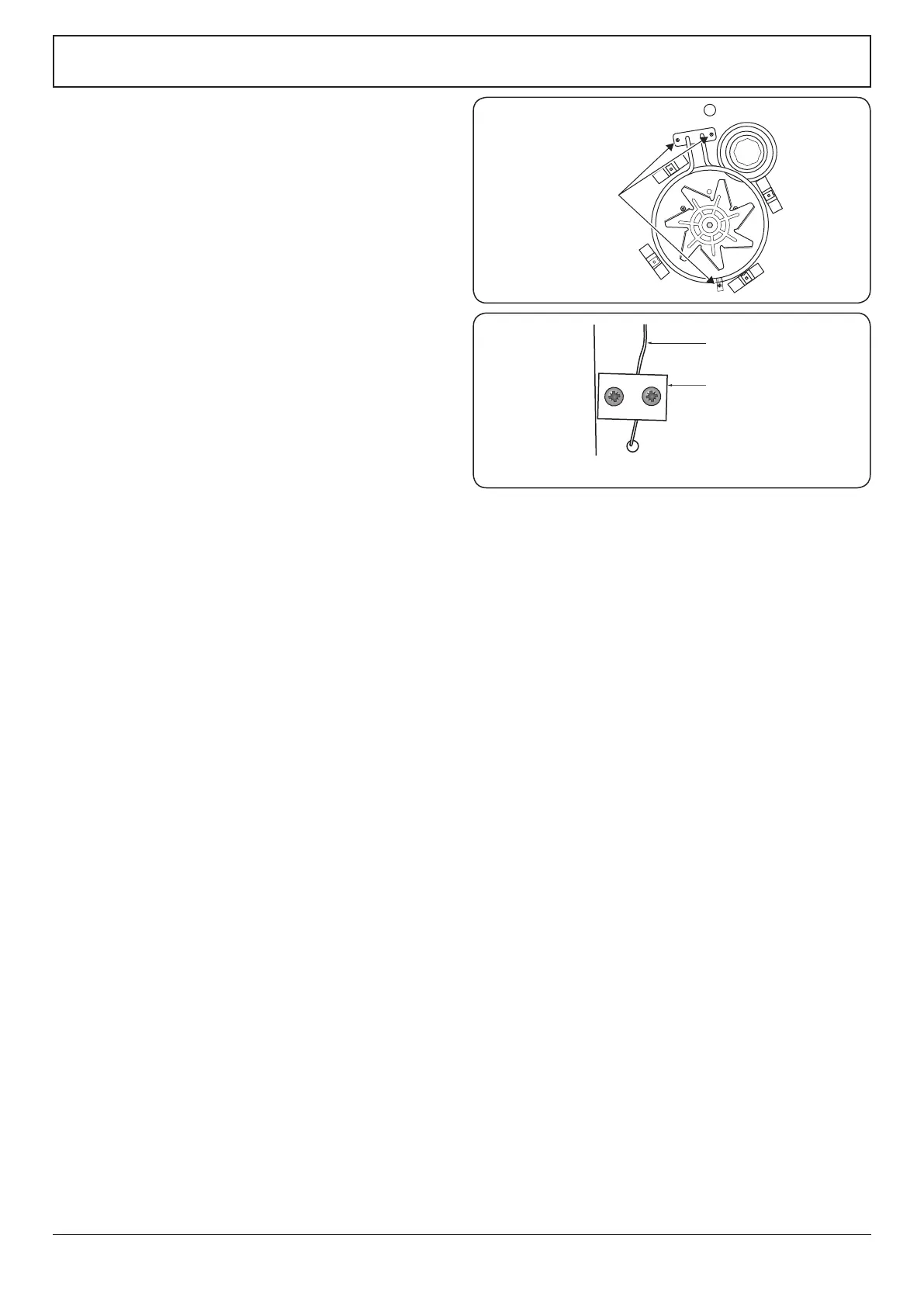
A
B
Element fixing screws
ArtNo.321-0005 Fan oven element
5.2 To Change the Oven Fan
DISCONNECT FROM THE ELECTRICITY SUPPLY.
Pull the cooker forward to gain access to the rear.
Remove the screws securing the electric cover to the
back sheet and remove the cover. Disconnect the
3terminals connected to the fan, noting their position.
Remove the oven inner back (see 5.1). Hold the fan
blade and remove the centre nut (left-hand thread),
2 brass washers, fan blade and circlip. Unscrew the fan
retaining nuts and washers (3 o each) and lift the fan
away from the rear of the cooker.
Fit the new fan and reassemble in reverse order. Check
the operation of the oven.
5.3 To Replace an Oven Element
DISCONNECT FROM THE ELECTRICITY SUPPLY.
Remove the oven inner back (see 5.1).
Remove the 2 screws from the top of the element and
the 1 from the bottom of the element (Fig. 9.4).
Carefully lift the element out, disconnecting the
terminals connected to the element (noting their
positions).
If it is not possible to disconnect the leads in this way,
pull the cooker forward to gain access to the rear,
remove the screws securing the electric cover to the
back sheet, remove the cover and disconnect the
terminals from the rear.
Fit the new element and reassemble in reverse order.
Check the operation of the oven.
5.4 To Remove an Oven Element Thermal Cut-Out
DISCONNECT FROM THE ELECTRICITY SUPPLY.
Pull the cooker forward to gain access to the cover
box. Undo the cover screws and lift clear. The cut-out
is located on the earth plate beside the oven element
connections. Disconnect the cut-out wiring. Undo the
xings that secure the cut-out to the earth plate and
remove.
Fit the replacement control and re-assemble in reverse
order.
5.5 To Replace an Oven Thermostat
DISCONNECT FROM THE ELECTRICITY SUPPLY.
Remove the control panel and hotplate (see 1.1 & 2.1).
Open the oven door and remove the oven furniture.
Main Oven
Pull the cooker forward to gain access to the cover box
at the rear of the cooker. Remove the 4 screws securing
the cover and lift clear. The oven thermostat capillary is
clamped to the oven back sheet with an earthing plate.
Remove the screws and plate (Fig. 9.5).
Tall Oven
The oven thermostat capillary is clamped to the right-
hand rear upright with an earthing plate.
Remove the thermostat phial cover (2 screws). Unclip
the thermostat phial from the clips in the oven back.
Fig. 9.5
A – Thermostat capillary, B – Earthing plate
Fig. 9.4