UPS System Architecture and Operating Modes
Figure 4.1
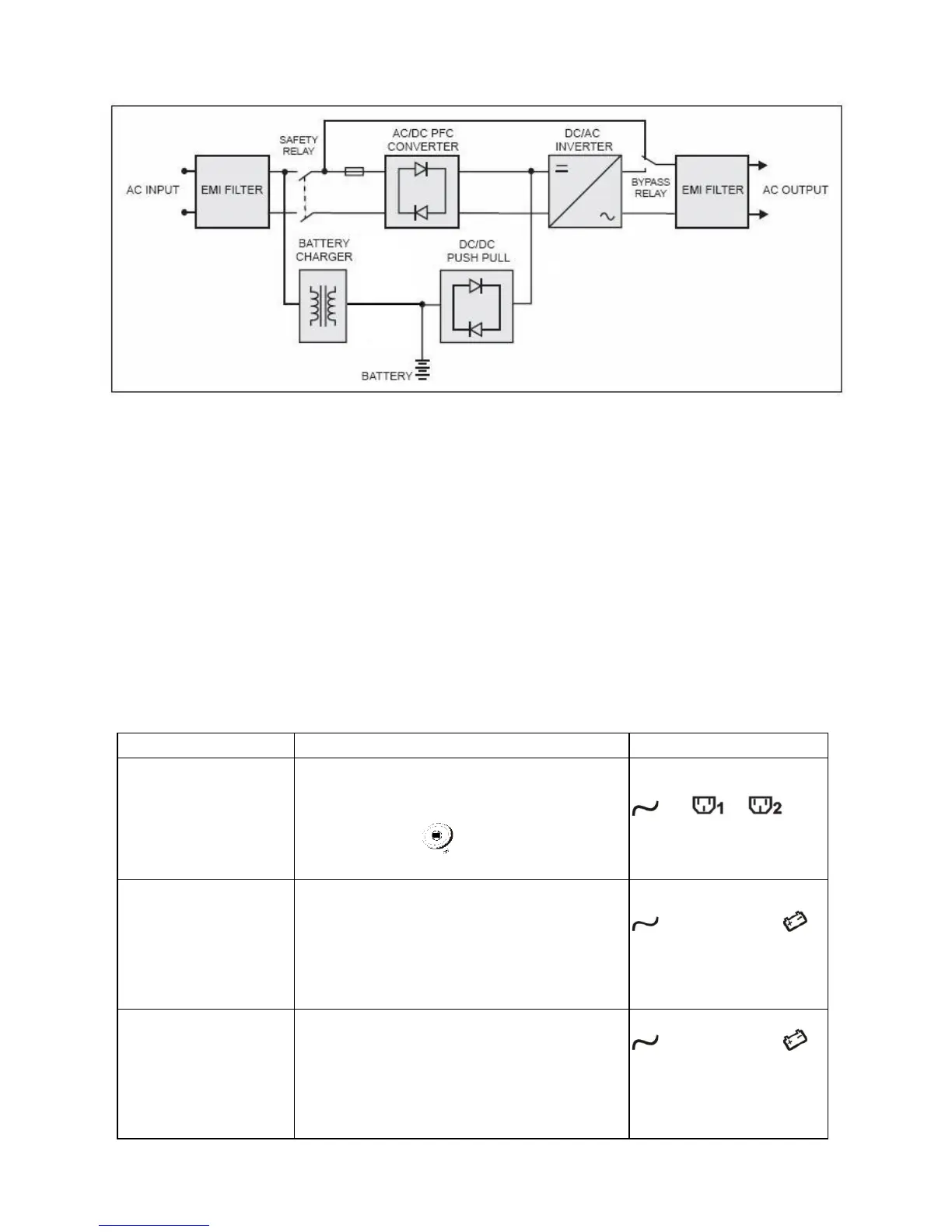
Figure 4.1 illustrates the True On-Line Double Conversion architecture of the
UPS system. The major modules consist of:
1) AC-to-DC power converter (rectifier) with PFC control circuit
2) DC-to-AC high frequency inverter
3) Intelligent battery charger
4) Bank of stationary, maintenance-free batteries
5) DC-to-DC push/pull converter control circuit
6) Static bypass
7) Input and output EMI filters
The table below provides a summary of the UPS operating modes under
various utility AC power source and battery conditions.
approximately 5 seconds, LEDs on the
panel will blink and fans will start. Press
the ON button for 1-5 seconds.
The UPS starts up normally.
、 、
LEDs will be lit.
Abnormal (under /
over-voltage or
absent)
Rectifier and charger stop operating.
Battery discharges via DC-DC boost
circuit and powers the inverter. Loads
continue to receive power
Alarm buzzer beeps every two
LED off. The
will be shown on
display.
Utility abnormal /
absent, or battery
voltage low
Rectifier and charger stop operating.
Battery discharges via DC-DC boost
circuit and powers the inverter. Alarm
buzzer beeps quickly, indicating battery
power is low and the output will be
LED off. The
and low battery
indication will be
shown on display.