"
4
/
3
4
"
8
/
7
45
124
90
1
"
16
/
9
"
4
/
3
19
3
1
7
A
4
2
8
5
0
3
9
B
6
"
16
/
1
4
"
8
/
7
52
124
90
2
"
16
/
9
"
4
/
3
19
3
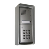
AMPLIFIED DOOR STATIONS
MD 100. 1 button module.
Be used in all intercom, telephone, intercom-
municating and video intercom systems.
Complete with electric door speaker amplified
in the two channels, receiving adjustable vol-
ume, call button and anodized aluminium front
plate. It can replace the MD11 and MD30 mod-
ule and use all the other accessories of the
Mody series.
MD 200. 2 buttons module.
Terminals
- ground
supply 13Vac/ 12-21Vdc-60mA
1 audio receiver
2 audio transmitter
C call push-buttons common
call push-buttons
name-plate lamp (24V-70mA)
1 Lamp terminals
2 Push-button terminal board
3 Common contact of call push-buttons
4 Terminals on stair light push-button
5 External volume adjustment
6 Terminal board for connection to the system
2
3
4
5
6
1
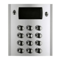
ACCESS CONTROL KEYPAD
FC52P.
Access control keypad with 12 digits and 2
relays for lock release. 4 programmable ac-
cess codes for each relay. Programmable door
opening time from 1 up 99 sec. for each relay
(or bistable operation of relay 1). Acoustic and
visual confirmation for entered keys, accepted
programming and for wrong codes.
Technical data
Power supply: 12Vac/dc ±10%
Stand-by current: 0.015A
Maximum current consumption: 0.1A
Contact ratings: 12Vac-5A.
Numbers of codes for relays 1: 4
Numbers of codes for relays 2: 4 or direct
activation
Activation time for each relay: from 1 to 99sec.
(or bistable relay 1)
Operating temperature: 0° ÷ +40°C
Maximum permissible humidity: 85% RH
Terminals
1 normally closed contact of relay 2
2 normally open contact of relay 2
3 common contact of relay 2
4 normally closed contact of relay 1
5 normally open contact of relay 1
6 common contact of relay 1
7 ground or alternate voltage input
8 positive or alternate voltage input
9-10 connection to optional door lock release
PUSH-BUTTONS MODY series
EXTERNAL DOOR STATIONS
Installation diagrams
For the installation of the MD100 and MD200
modules see the installation diagrams for sys-
tems with one entrance.
12Vac
12Vdc
door
release
relay 1 relay 2
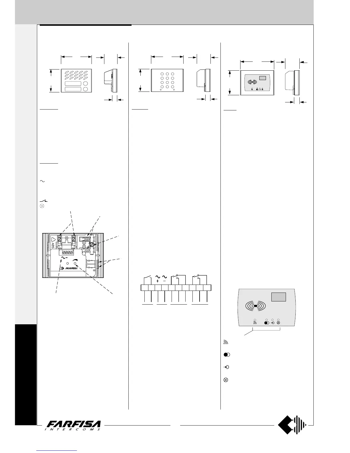
PROXIMITY READER FOR ACCESS
CONTROL
FP52.
This article allows for the activation of 2 relays
by means of keytags or electronic ISO cards
based on transponder technology.
Programmable activation time from 1 to 63
seconds for every relay. 4 user cards and 1
master card supplied with the product. Acoustic
and visual control signals and 3-digit display to
view numbers and codes during set-up and
operation.
Technical data
Power supply 12Vac/dc ±10%
Stand-by current 0.1A
Maximum current consumption 0.25A
Contact ratings 24Vac - 2A
Max. number of cards 490
Max. number of Master cards 10
Number of relays 2
Relay time 1 to 63 sec.
Minimum recognition distance 3 cm
Maximum recognition time 1 sec.
Operating temperature 0° ÷ +40°C
Maximum permitted humidity 85% RH
Terminals
+/A positive or alternate current input
-/A ground or alternate current input
PB door open button
NC2 normally closed contact of relay 2
NA2 normally open contact of relay 2
C2 common terminal of relay 2
NC1 normally closed contact of relay 1
NA1 normally open contact of relay 1
C1 common terminal of relay 1
Card recognition LED. It turns ON during
card recognition.
Relay activation LED. It indicates relay de-
activation (red) or activation (green).
Program LED. It turns ON during system
programming.
Card cancellation and system setup LED.
It turns ON during Master or user card can-
cellation and system setup.
10987654321