156
(MT11 - Gb2012)
4+1
INTERCOMS *
7+1
VIDEOINTERCOMS
Si 23MO/1
E
X
-
K
M
-
S
T
-
P
T
PRS240
9
9
FP
FP
7
PT510E
C+
ST720
KM810
EX320
EX310
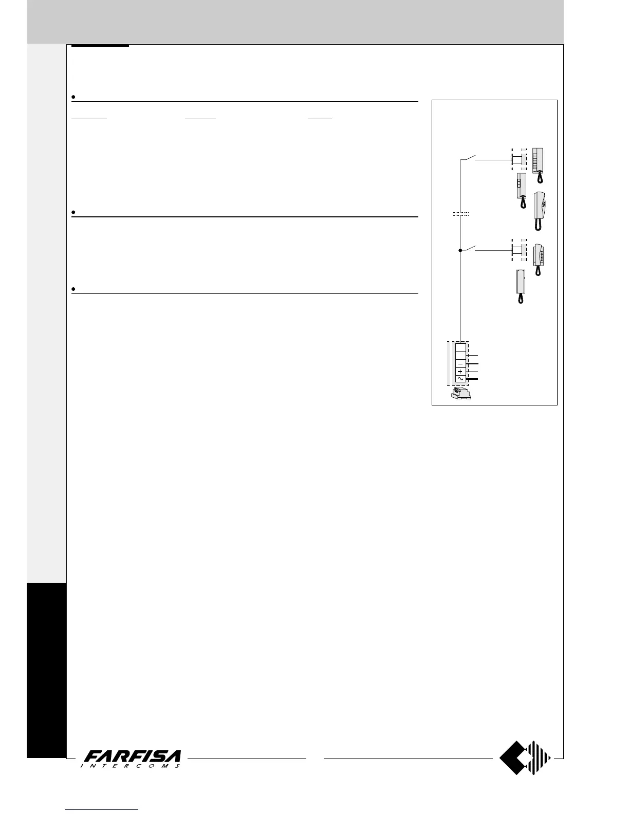
Floor call
This work diagram allows for differ-
entiating the floor-call from the call
from the push-button panel.
Floor-button
Floor-button
INTERCOMS CONNECTED TO 3 AUTOMATICALLY SWITCHED EXTERNAL DOOR STATIONS
EXTERNAL DOOR STATIONS
PROFILO series MATRIX series MODY series
... PL71÷PL73 ... MA71÷MA73 ... MD71÷MD74
3 PL81÷PL89 3 MAS61÷MAS63 (
1
)3MD81÷MD812
3 PL91÷PL99 * 3 MA91÷MA93 * 3 MD91÷MD912 *
3 PL10P÷PL12P 3 MAS10P÷MAS12P 3 MD10÷MD124
... PL21÷PL228 ... MAS22-MAS24 ... MD21÷MD228
... PL20, PL50 ... MAS20 ... MD20, MD50
3 MD30
INTERNAL STATIONS
... EX310 Exhito series intercom with 2 call buttons
... EX320 Exhito series modular intercom
... KM810W Compact series intercom with 1 call button
... ST720W Studio series modular intercom
... PT510EW Project series intercom with 1 call button
VARIOUS ARTICLES
2 1473 Exchanger
1 PRS240 Power supply with electronic ringing generator
3 PA ** Door release push-button (optional)
3 SE ** Electric door lock (12VAC-1A)
... Refers to number of users.
(
1
) Or MA61÷MA63.
* Rain shelters are used instead of back boxes and hood covers.
** Articles not supplied by ACI Farfisa.
Working instructions.
As the basic system described on page 183, with the following variations:
- The audio functions and door lock opening are automatically switched to the door station which has
made the call and remain in this state until a call from another entrance is received.
Notes
- For the connection of name-plate lamps, read notes 6, 7 and 8 of the installation instructions on page
146.
- For wires dimensioning refer to the installation recommendations and table on page 146.