160
(MT11 - Gb2012)
4+1
INTERCOMS *
7+1
VIDEOINTERCOMS
Si 26MO/2
E
X
-
K
M
-
S
T
-
P
T
ONE WAY INTERCOM SYSTEM WITH SECONDARY DOOR STATIONS AND 1 MAIN COMMON STATION (multiple
entrance)
Main DOOR STATION
PROFILO series MATRIX series MODY series
... PL71÷PL73 ... MA71÷MA73 ... MD71÷MD74
1 PL81÷PL89 1 MAS61÷MAS63 (
1
)1MD81÷MD812
1 PL91÷PL99 * 1 MA91÷MA93 * 1 MD91÷MD912 *
1 PL10P÷PL12P 1 MAS10P÷MAS12P 1 MD10÷MD124
... PL21÷PL228 ... MAS22-MAS24 ... MD21÷MD228
... PL20, PL50 ... MAS20 ... MD20, MD50
1 MD30
Secondary DOOR STATIONS
PROFILO series MATRIX series MODY series
X PL71 X MA71 X MD71
X PL81 X MAS61 (
1
)XMD81
X PL91 * X MA91 * X MD91 *
X PL11P X MA11P X MD11
X MD30
INTERNAL STATIONS
... EX310 Exhito series intercom with 2 call buttons
... EX320 Exhito series modular intercom
... KM810W Compact series intercom with 1 call button
... ST720W Studio series modular intercom
... PT510EW Project series intercom with 1 call button
VARIOUS ARTICLES
X 1473 Exchanger
1+X PRS240 Power supply with electronic ringing generator
1+X PA ** Door release push-button (optional)
1+X SE ** Electric door lock (12VAC-1A)
... Refers to number of users.
X Refers to the number of stairways.
(
1
) Or MA61÷MA63.
* Rain shelters are used instead of back boxes and hood covers.
** Articles not supplied by ACI Farfisa.
Working instructions.
As the basic system described on page 183, with the following variations:
- The audio functions and door lock opening are automatically switched to the door station
which has made the call and remain in this state until a call from another entrance is
received.
- Services to secondary door stations are independent and can be operated at the same
time.
Notes
- For the connection of name-plate lamps, read notes 6, 7 and 8 of the installation
instructions on page 146.
- For wires dimensioning refer to the installation recommendations and table on page
146.
PA
SE
230V
127V
0
3
45789
PRS240
1473
MD100
RP100
UP11
UP100
2
1
8b
9b
7b
6 9a8a7a
C
P
X
C+
2
1
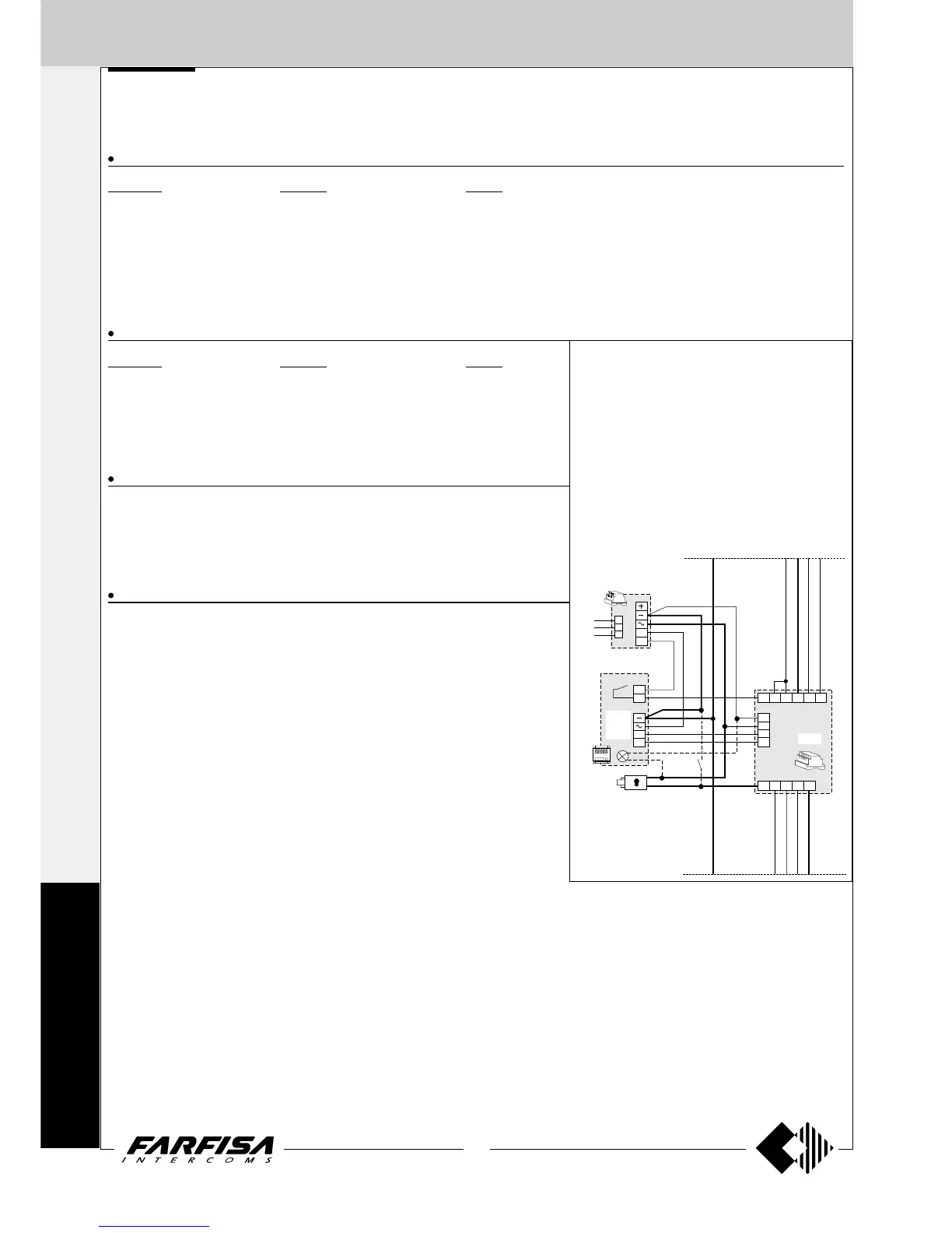
Application diagram
When using MD100, RP100, UP11 and UP100
amplified external door stations as one-way second-
ary door stations, place this diagram on the diagram
on page 161 and line it up with the riser.
Warning.
- Cut jumper W1 in the RP100 external door stations.
- In UP series external door stations do not connect
and insulate the yellow wire.
- For alternate current wires refer to note 6 of the
installation instructions on page 146.