194
(MT11 - Gb2012)
Si 41MO/5
4+1
INTERCOMS *
7+1
VIDEOINTERCOMS
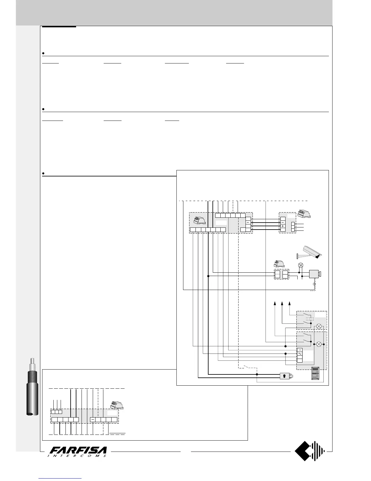
VIDEO INTERCOM SYSTEM CONNECTED TO ONE EXTERNAL DOOR STATION WITH SURVEILLANCE
CAMERA
INTERNAL STATIONS
ECHOS series EXHITO series COMPACT series STUDIO series
... EH9100CT/CW ... EX3100C ... KM8100W ... ST7100CW
EH9160CT/CW EX3160C KM8600W ST7100W
... 9083 EX3160 KM8800W ... ST720W
... WA9100T/W ... WB3160 ... WB8600 ... WB7100
... TA9160 ... TA3160 ... 8083 ... WB700
... TA7100
... TA700
EXTERNAL DOOR STATIONS
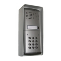
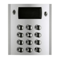
PROFILO series MATRIX series MODY series
... PL71÷PL73 ... MA71÷MA73 ... MD72÷MD74
1 PL81÷PL89 ... MAS61÷MAS63 (
1
)1 MD82÷MD812
1 PL91÷PL99 * 1 MA91÷MA93 * 1 MD92÷MD912 *
1 PL10P÷PL12P 1 MAS10P÷MAS12P 1 MD10÷MD124
... PL21÷PL228 ... MAS22-MAS24 1 MD30
... PL20, PL50 ... MAS20 ... MD21÷MD228
... MD20, MD50
VARIOUS ARTICLES
... DV2-DV4Video distributors
1 1281 Power supply
1 1282E Timer
1 1471 Relay unit
1 TVT.. CCTV camera
1 H.. Lens with or without autoiris
1 CU.. Outdoor heated housing
1 AST.. Bracket for camera or housing
1 APS.. Power supply for camera
1 LL** Lamp with maximum power 800W (optional)
1 PA ** Door release button (optional)
1 SE ** Electric door lock (12Vac-1A)
... Refers to number of users.
(
1
) Or MA61÷MA63.
* The rain shelter is used in the place of the back box and
hood cover.
** Articles not supplied by ACI Farfisa.
Working instructions. See page 218.
Notes
- If the control switching ON is necessary, connect terminal 4
of the timer (dashed wire).
- For audio compatibility we do not suggest to connect door
stations MODY series with internal devices ECHOS series.
- For the connection of name plate lamps read notes 6, 7 and
8 of the installation instructions on page 146.
- For wires dimensioning and video connection refer to the
installation instructions and table on pages 146÷148.
- For one-way systems connect the coaxial cable to the moni-
tor bracket directly, without using the video distributor.
- For the selection of CCTV equipment or other types of push-
button panels see the general catalogue.
2
3
1471
6
5
CU..
AST..
APS..
230V
LL
TVT..
H..
2
1
X2 X3 Xn
MD7.
MD100
MD200
MD2..
PA
230V
127V
0
1282E
2D1D 3D 5 7
1281
4
I
A
F
X
SC+
1
2
H
SE
IV
H
A
3+
Connection of 1281E power supply-timer instead of
1281 plus 1282E.
By adding 1281E to the schematics on pages 194 and
195 instead of 1281 plus 1282E, the system working will
modify as follows:
- switching-OFF at the end of the timing only
- no control switch-ON interruption with the video inter-
coms during external audio-video connection. If the
service is necessary, add 1471 relay in order to inter-
rupt conductor 4.
230V
127V
0
1281E
X
S
H
F
C+
5
A
4
3+
only for
si41mo5
When using MD100 and MD200 amplified external door stations, it is
advisable to place this diagram on the diagram of page 195 and line it up
with the riser.
For AC powered wires refer to the indications on page 146.