196
(MT11 - Gb2012)
Si 42MO/1
4+1
INTERCOMS *
7+1
VIDEOINTERCOMS
VIDEO INTERCOM SYSTEM CONNECTED TO TWO EXTERNAL DOOR STATIONS
INTERNAL STATIONS
ECHOS series EXHITO series COMPACT series STUDIO series
... EH9100CT/CW ... EX3100C ... KM8100W ... ST7100CW
EH9160CT/CW EX3160C KM8600W ST7100W
... 9083 EX3160 KM8800W ... ST720W
... WA9100T/W ... WB3160 ... WB8600 ... WB7100
... TA9160 ... TA3160 ... 8083 ... WB700
... TA7100
... TA700
EXTERNAL DOOR STATIONS
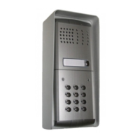
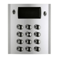
PROFILO series MATRIX series MODY series
... PL71÷PL73 ... MA71÷MA73 ... MD72÷MD74
2 PL81÷PL89 ... MAS61÷MAS63 (
1
)2 MD82÷MD812
2 PL91÷PL99 * 2 MA91÷MA93 * 2 MD92÷MD912 *
2 PL40PC÷PL42PC 2 MAS42C-MAS43C 2 MD10÷MD124
PL40P÷PL42P MAS42-MAS43 2 MD41
... PL21÷PL228 ... MAS22-MAS24 2 MD30
... PL20, PL50 ... MAS20 ... MD21÷MD228
... MD20, MD50
VARIOUS ARTICLES
... DV2-DV4 Video distributors
1 1281 Power supply
1 1282E Timer
1 1273TV Exchanger
2 PA ** Door release button (optional)
2 SE ** Electric door lock (12Vac-1A)
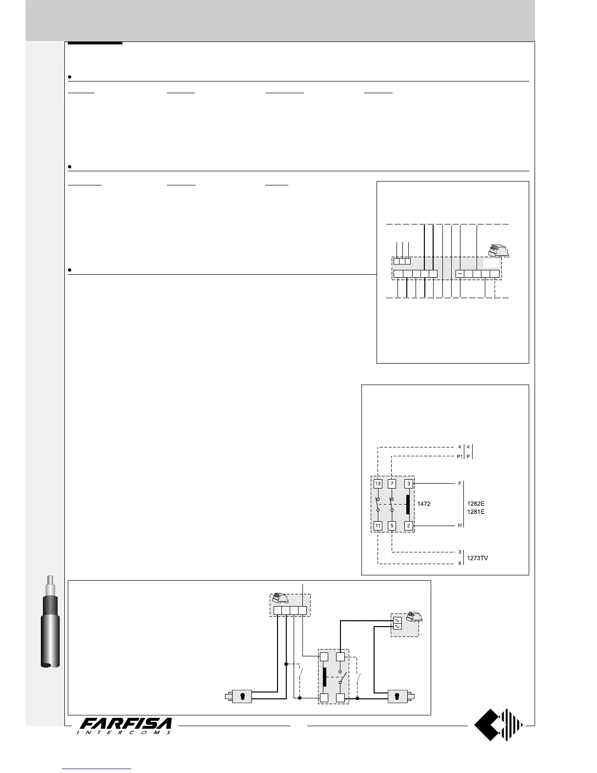
Control switching ON deactivation
To deactivate the monitoring function during the
conversation and to keep it only when the system is
in standby, it is necessary to install a 2-exchange
relay (type 1472) and connect it as shown on the
diagram.
Connection of 1281E power supply-timer
instead of 1281 plus 1282E.
By adding 1281E to the schematics on page
197 instead of 1281 plus 1282E, the system
working will modify as follows:
- switching-OFF at the end of the timing only.
to the video-
intercoms
... Refers to number of users.
(
1
) Or MA61÷MA63.
* The rain shelter is used in the place of the back box and hood cover.
** Articles not supplied by ACI Farfisa.
Working instructions.
As the basic system described on page 218, with the following variations:
- The audio-video functions and door lock opening are automatically switched to the door
station which has made the call (or control switching ON) and remain in this state until a
call from another entrance is received.
Notes
- If monitoring function is required it is necessary to connect the dashed conductors and:
-Echos series - verify that jumper J5, located on the back of videointercom, is in the
position 2-3;
-Exhito series (possibility of monitoring only the “a” entrance);
-Compact series - connect together terminals 1C and PC on the wall bracket;
-Studio series - connect together terminals 1C and PC on the wall bracket.
- For audio compatibility we do not suggest to connect door stations MODY series with
internal devices ECHOS series.
- For the connection of name plate lamps read notes 6, 7 and 8 of the installation
instructions on page 146.
- For wires dimensioning and video connection refer to the installation instructions and
table on pages 146÷148.
- For one-way systems connect the coaxial cable to the monitor bracket directly, without
using the video distributor.
- For other types of push-button panels see the general catalogue.
230V
127V
0
1281E
X
S
5
A
H
4
3+
F
C+
PA
PA
SE
SE
PRS210
1282E
1281E
22
1
5
1471
S
2
6
A
5
2
3
F
Connection of 2 door locks with simulta-
neous opening
If it is necessary to operate the 2 door locks
of the system at the same time, you must:
- add a 12Vac transformer with suitable
power (type PRS210)
- add a 12Vac relay (type 1471)
- make the connections as shown in the
diagram below.
to 5 of the videointercoms