227
(MT11 - Gb2012)
4+1
INTERCOMS *
7+1
VIDEOINTERCOMS
ONE-WAY additional diagrams
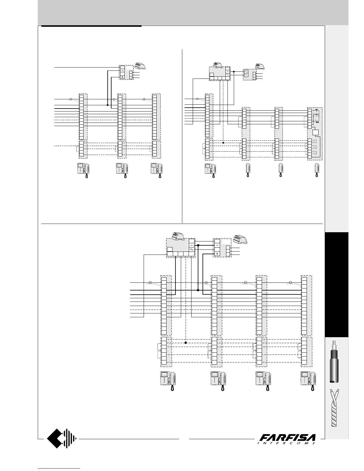
3 VIDEO INTERCOMS WITH INTERCOMMU-
NICATING SERVICE
VC1 VC2 VC3
ST7100+
WB7100+
ST720+
WB700+
ST701
ST7100+
WB7100+
ST720+
WB700+
ST701
ST7100+
WB7100+
ST720+
WB700+
ST701
8
V
M
F
H
1
2
3
4
5
9M
PC
P
1C
9R
8
V
M
F
H
1
2
3
4
5
9M
PC
P
1C
9R
230V
127V
0
1281
A
I
8
V
M
F
H
1
2
3
4
5
9M
PC
P
1C
9R
9
C
P1
C
P2
P1
C
9
C
P2
P1
C
P2
C
9
VC1
ST7100+
WB7100+
ST720+
WB700+
ST701
RL37
8
V
M
F
H
1
2
3
4
5
9M
PC
P
1C
9R
9
C
P1
C
P2
C
P3
P1
C
P2
C
9A
C
P3
P1
C
9A
C
P2
C
P3
9R
79M
H
B
9P
CT3CT2CT1
1
2
3
5
9
3A
1
2
3
5
9
3A
1
2
3
5
9
3A
ST
704
P1
C
P2
C
P3
C
9A
ST720+
ST701+
ST704
ST720+
ST701+
ST704
ST720+
ST701+
ST704
1
2
3
230V
127V
0
PRS210
IV
1 VIDEO INTERCOM AND 3 INTERCOMS WITH INTERCOMMUNI-
CATING SERVICE
to terminal IV
of the 1282E
S
T
U
D
I
O
to terminal 7 of
the 1282E or
PRS240
VC1 VC2 VC3 VC4
ST7100+
WB7100+
ST720+
WB700+
ST701
ST7100+
WB7100+
ST720+
WB700+
ST701
ST7100+
WB7100+
ST720+
WB700+
ST701
ST7100+
WB7100+
ST720+
WB700+
ST701
8
V
M
F
H
1
2
3
4
5
9M
PC
P
1C
9R
8
V
M
F
H
1
2
3
4
5
9M
PC
P
1C
9R
8
V
M
F
H
1
2
3
4
5
9M
PC
P
1C
9R
230V
127V
0
RL37
1281
A
I
IV
8
V
M
F
H
1
2
3
4
5
9M
PC
P
1C
9R
9
C
P1
C
P2
C
P3
P1
C
9
C
P2
C
P3
P1
C
P2
C
9
C
P3
P1
C
P2
C
P3
C
9
9R
79M
H
B
9P
4 VIDEO INTERCOMS WITH INTERCOMMU-
NICATING SERVICE
Notes
- On the videointercom bracket to move the jumper J1 from position 2-3 to
1-2 (see page 107) for the intercommunicating service.
- Read notes 1, 3 and 4 of page 219.
Notes
- On the videointercom bracket to move the jumper J1 from position 2-3 to
1-2 (see page 107) for the intercommunicating service.
- Read notes 1, 3 and 4 of page 219.
Notes
- On the videointercom bracket to move the jumper J1 from position 2-3 to
1-2 (see page 107) for the intercommunicating service.
- Read notes 1 and 4 of page 219.