Crane folded into the rest position
We introduced the handling of the crane in the rest condition. When you fold
the crane to its rest position, the angle sensor detects a value around 90°, thus
disabling the lifting manoeuvres. In order to obviate to this condition, when
turning on the crane, if it exceeds the limit values, the message "CRANE
FOLDED" will be displayed on the main unit. At this point the only manoeuvre
allowed is the folding of the outer ram (according to the manual for Use and
Maintenance, this is the first manoeuvre to be executed when unfolding the
crane). If during this manoeuvre the pressure in the outer ram goes down for
at least two seconds, then the crane is considered in rest condition, the mes-
sages "CRANE FOLDED" disappears and all the manoeuvres are allowed.
NOTE: the message "CRANE FOLDED" is displayed also when the crane is
turned off with the booms in "LIFTING BLOCK" condition and then the crane
is turned back on; descend the outer boom below the horizontal line in order to
remove the message.
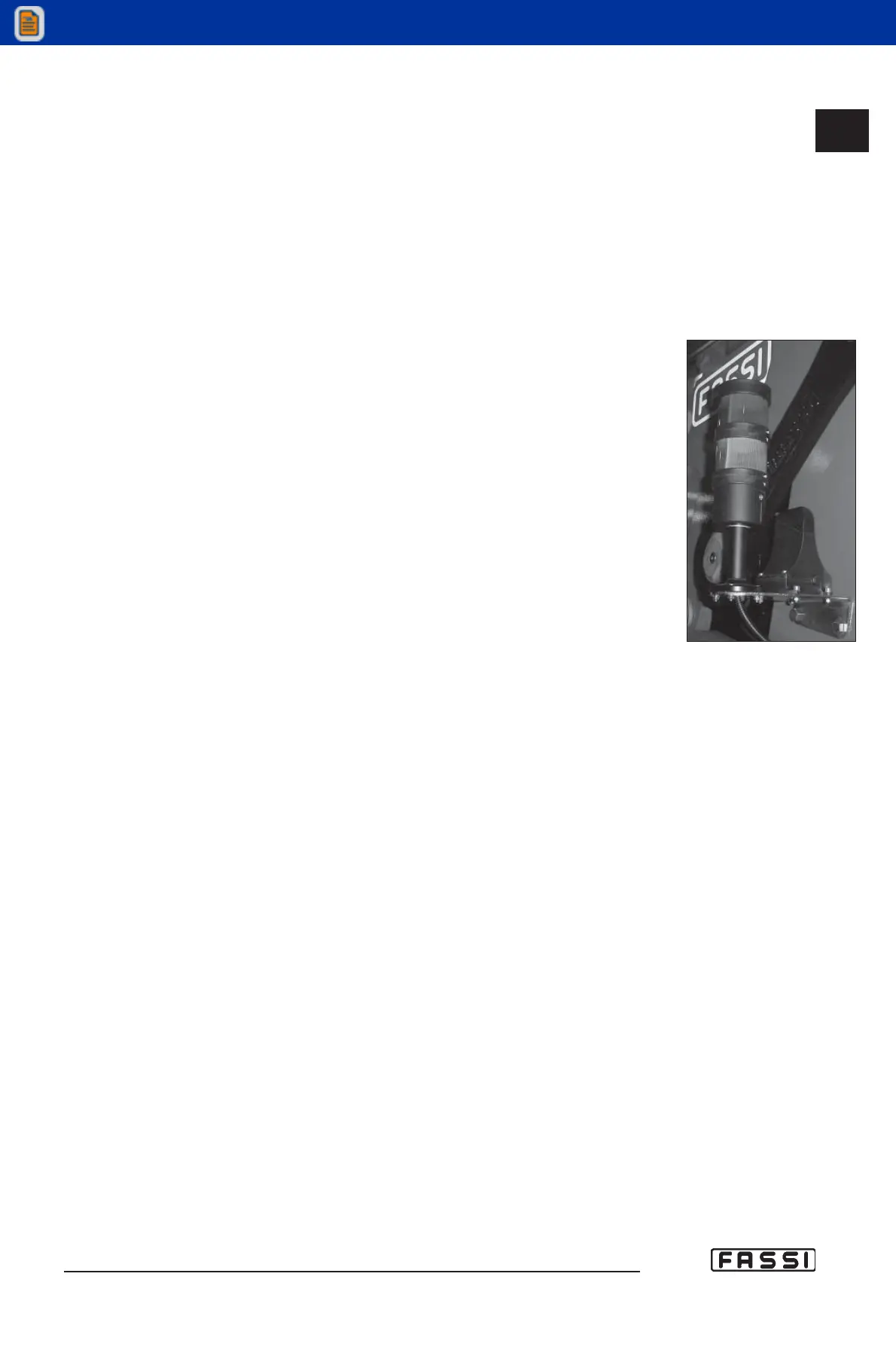
16.4.5 Visual indicator yellow/red light
The crane is fitted with visual indicator of the following signals: yellow light
upon reaching 90% and red light upon activation of the lifting moment limiting
device. The visual indicator (fig. 4) is in full view on the structure of the crane or
of the vehicle.
NOTE: If the radio-remote control is off or however one cannot comunicate with
the crane (receiver) the yellow and red warning lights alternately flash.
16.5 Lifting moment limiting device for two working
sectors
In case of one sector of the working area with reduced stability of the vehicle
(e.g. sector in front of vehicle cab) the limiting device can be provided with a
special function which allows to operate with a reduction of the intervention
level. The reduction of the intervention level reduces the crane capacity values
and this reduction value is defined in the vehicle stability calculation.
Consequently the working area is divided in one sector (e.g. body side) where
the crane works according to the capacity plate values and another sector (e.g.
cab side) where it works with reduced capacity values. The device has conse-
quently two intervention levels which are activated in relation to the sector of
the crane working area always securing the vehicle stability.
(!) ATTENTION (!)
If the rotation stops by going through the working zone where the crane
can operate according to the capacity plate values to the one where it
can operate according to the reduced values, it means that one of the fol-
lowing conditions is reached:
- rotation of a load bigger than the one admitted in the reduced
sector defined in the vehicle stability calculation;
- rotation without load applied but with (at least) one of the inner,
outer rams of the crane or the jib (if fitted) extended and pressuri-
sed at the stroke end.
The following manoeuvres are allowed:
- the opposite rotation;
- the manoeuvres allowed by the limiting device.
If a reduction of capacity is necessary because of insufficient stability of the
complete unit, new capacity plates must be fixed giving the derated capacity in
accordance with the final stability test.
(!) ATTENTION (!)
Always check carefully that the vehicle is perfectly stable, paying special
attentino to the area immediately in front of the driver's cabin as this is
usually less stable.
16.5
CONTROLS TO OPERATE
THE CRANE
GR4_5 - EVOLUTION
fig. 4
 Loading...