BASIC PANEL
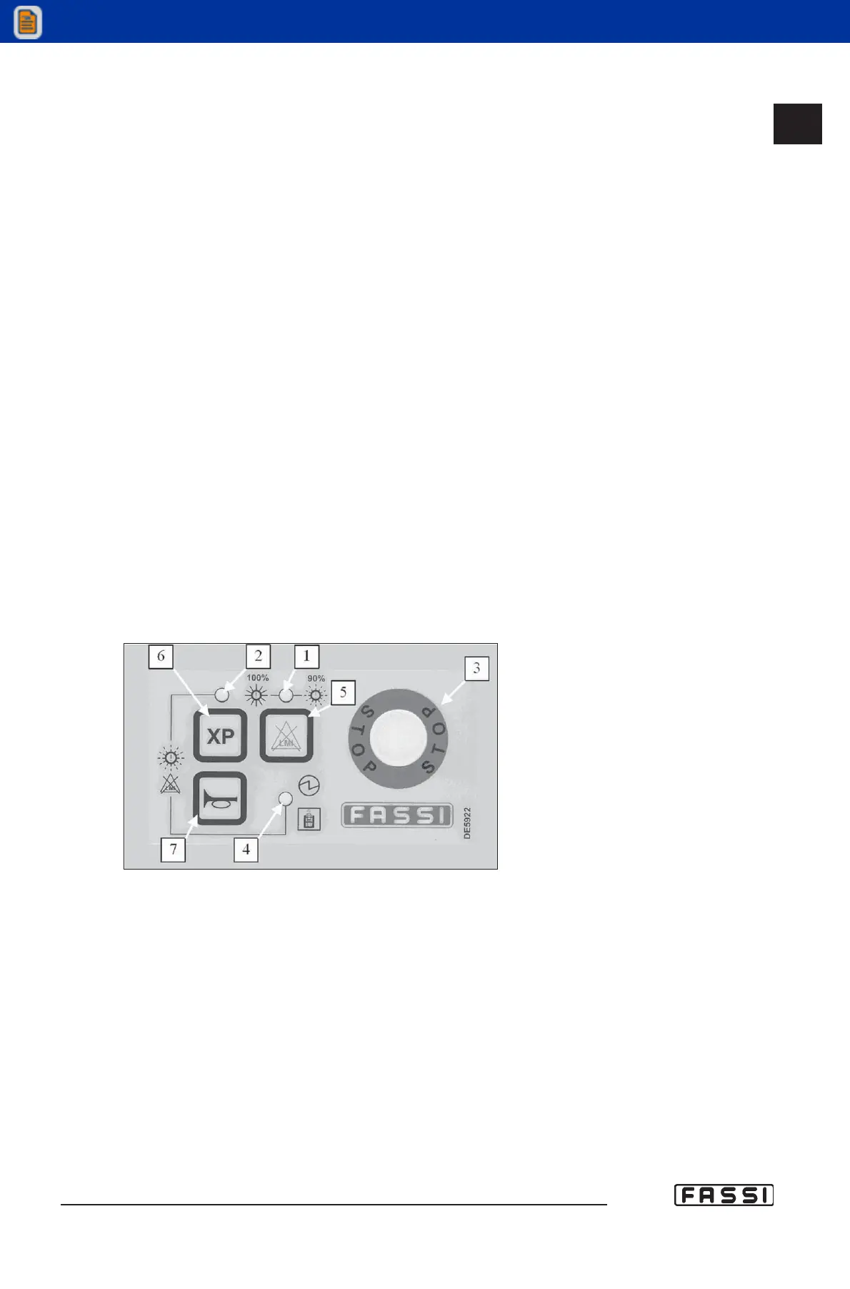
Refer to fig. 3 to identify the various components of the panel:
1 Green, yellow and red led band signalling the load percentage as com-
pared to the capacity plate. Green light load between 0 and 90%.
Yellow light load between 90 and 100%. Red light load higher than 100%
(activation of the lifting moment limiting device). The red light can also
signal "warning" if flashing, or "alarm" if fixed.
2 Orange light signalling that the XP device is enabled.
3 Mushroom-shaped emergency button (always active).
4 Green light signalling tension in he panel; if flashing, it indicates the
presence of the operator in the third control station.
5 Control button for the temporary exclusion of the lifting moment limiting
device, and for the reset of the messages "alarm" and "warning".
6 "XP" device push-button.
7 Audible alarm push button (see instructions and warnings).
2-4 Lights 2-4 are flashing during the exclusion procedure of the lifting moment
limiting device.
16.3
CONTROLS TO OPERATE
THE CRANE
GR4_5 - EVOLUTION
fig. 3