10
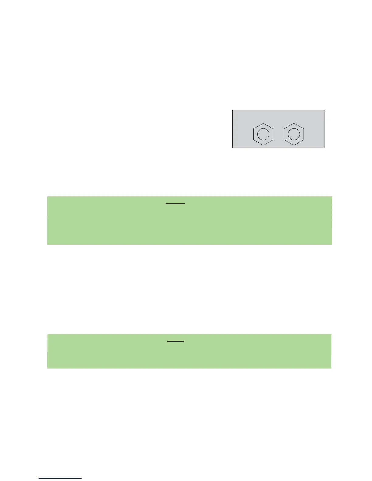
CONDENSER WATER
OUT
IN
Bulkhead Fittings, Condenser
Figure 5.5
A. Connect a backflow prevention assembly to the water inlet of the unit (see Figure 5.2). A backflow
prevention assembly is available from FBD under PN 12-2272-0001.
B. Fabricate a 3/8 inch supply line for connecting the unit to a potable water supply (a 3/8” barb by 1/4”
flare nut fitting will be required).
C. Install a shutoff valve in the water line as close to the unit as practical and convenient. The use of
a water filter is recommended.
D. Clear the line by running a minimum of two (2) gallons (7.57 liters) of water through the line before
attaching the line to the unit.
E. Connect the line to the bulkhead fitting labeled “WATER IN” located at the rear of the unit (see
Figures 5.2, 5.3 or 5.4, as appropriate).
F. For water cooled units:
1. Fabricate another water line from the main water line and
connect to the bulkhead fitting labeled “Condenser In” (a
3/8” barb by 3/8” flare nut fitting will be required) (see
Figure 5.5).
2. Fabricate a 3/8 inch drain line for connecting to the
location labeled “Condenser Out” (a 3/8” barb by 3/8” flare
nut fitting will be required) (see Figure 5.5).
G. Route the drain line to a drain location.
H. Do not turn water on at this time.
5.2 CO2 SUPPLY
NOTE:
The CO2 supply may come from either an independent tank/regulator or a bulk CO2 system. If
connected to a bulk CO2 system, install a shutoff valve and a secondary supply regulator [to be set at
70-72 psig (482.6-496.4 kPag)] in the line. Ensure that the CO2 line comes directly from the main
branch on the bulk supply and is not branched off down line. Failure to do so may starve the unit
of CO2 flow and cause performance problems.
A. Fabricate a 3/8 inch supply line for connecting the unit to a CO2 supply.
B. Connect the supply line to the CO2 bulkhead fitting labeled “CO2 IN” located at the rear of the unit
(see Figure 5.2). A 3/8” barb by 1/4” flare nut fitting will be required to make connection.
C. Splice a barb “cross” into the CO2 supply line and run two (2) lines to the syrup pump CO2 inlets.
Or
If Figal tank will be utilized, splice a barb “cross” into the CO2 supply line and run two (2) lines to tank
location and install CO2 tank couplers to end of lines.
D. Do not turn on the CO2 at this time.
5.3 SYRUP SUPPLY
The unit may be connected to either a BIB (Bag-in-Box) or a five-gallon syrup supply (figal). Use the
appropriate connection method below.
NOTE
Installations requiring long runs of tubing [25 feet or more (7.62 meters)] may encounter
pressure fluctuation problems. The machine’s sensors may indicate that the machine is out of syrup,
water, or CO2. To avoid pressure fluctuations, consider the following solutions.
A. Increase the tubing size to 1/2 inch diameter.
B. Install booster pumps in the supply lines. Use a vacuum regulating valve with syrup booster
pumps.
C. Increase primary CO2 regulator pressure from bulk or tank CO2 to 105 - 120 psig (723.9 to
827.4 kPag). A secondary regulator will be necessary for syrup pumps to avoid exceeding
manufacturer’s recommended operating pressures. Set the secondary regulator to 70-72 psig
(482.6-496.4 kPag).