FEMA ELECTRÓNICA . Series C . C40-D
12
Ranges
of measure
Scale
by default
Scalable
Jumper ‘S’
(see secon 1.9)
Jumper ‘T’
(see secon 1.9)
Accuracy
(% of reading)
0 to 5 K 5.000
from 9999
to -1999
F H K
4-5
<1.5% of
reading
0 to 50 K 50.00 F K
Table 17 - Ranges of measure for resistances
• Measuring resisve signals
The instrument accepts the measure of resistances and
provides two ranges of measure from 0 to 5 K and from
0 to 50 K.
• Compensang the resistance of the signal wire
Resistances are measured with 2 wires system. To compensate for
the possible error introduced by the resistance of the signal wires,
the instrument allows to congure a xed number of counts to be
added to the reading, both in posive or negave. This is done with
the parameter ‘Oset reading’ (‘oFFS’) (see secon 1.22).
• Scaling
The instrument allows to scale the reading to 4 digits (9999 / -1999)
with congurable decimal point to any posion. The ‘second scaling’
funcon can also be used (see secon 1.25).
1.18 Measuring resistances
• Response mes
The response me to a signal step is 300 mSeconds, independent of
the signal range selected.
• Terminal 5 ‘mulfuncon’ - External control
Terminal 5 remains congured as ‘EK’ external control funcon. See
secon 1.9 for a list of available funcons.
• Start-up, connecons and jumpers
For instrument start-up follow the steps listed at secon 1.7. Signal
connecons are indicated at secon 1.5. Locaon for internal jump-
ers is indicated at secon 1.9.
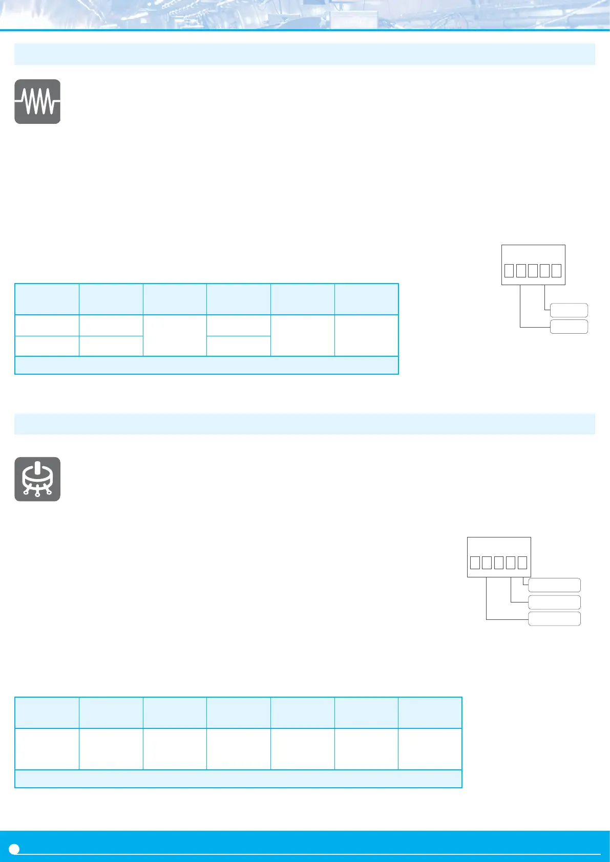
See below connecons for resistance measures :
res +
res -
12345
Nominal
pot. value
Ranges
of measure
Scale
by default
Scalable
Jumper ‘S’
(see secon 1.9)
Jumper ‘T’
(see secon 1.9)
Accuracy
(% FS)
from 500 R
up to 20 K
0 to 100 % 0/100.0
from 9999
to -1999
A 2-3 <0.5%
Table 18 - Ranges of measure for potenometers
• Measuring potenometers
The instrument accepts the measure of 3 wire poten-
ometers, with a single default range of 0/100 % of the
potenometer span.
• Scaling
The instrument allows to scale the reading to 4 digits (9999 / -1999)
with congurable .
• Response mes
The response me to a signal step is 300 mSeconds, independent of
the signal range selected.
• Terminal 5 ‘mulfuncon’ - ‘Vexc’
To measure potenometer signals, set internal jumper ‘T’ at posion
2-3 (see secon 1.9). Terminal 5 will be assigned to a +5 Vdc excita-
on voltage for the potenometer.
1.19 Measuring potenometers
• Start-up, connecons and jumpers
For instrument start-up follow the steps listed at secon 1.7. Signal
connecons are indicated at secon 1.5. Locaon for internal jump-
ers is indicated at secon 1.9.
See below connecons for measure of potenometers ::
Signal
Pot- (comm.)
Pot+ (5 Vdc)
12345
 Loading...