FEMA ELECTRÓNICA . Series C . C40-D
26
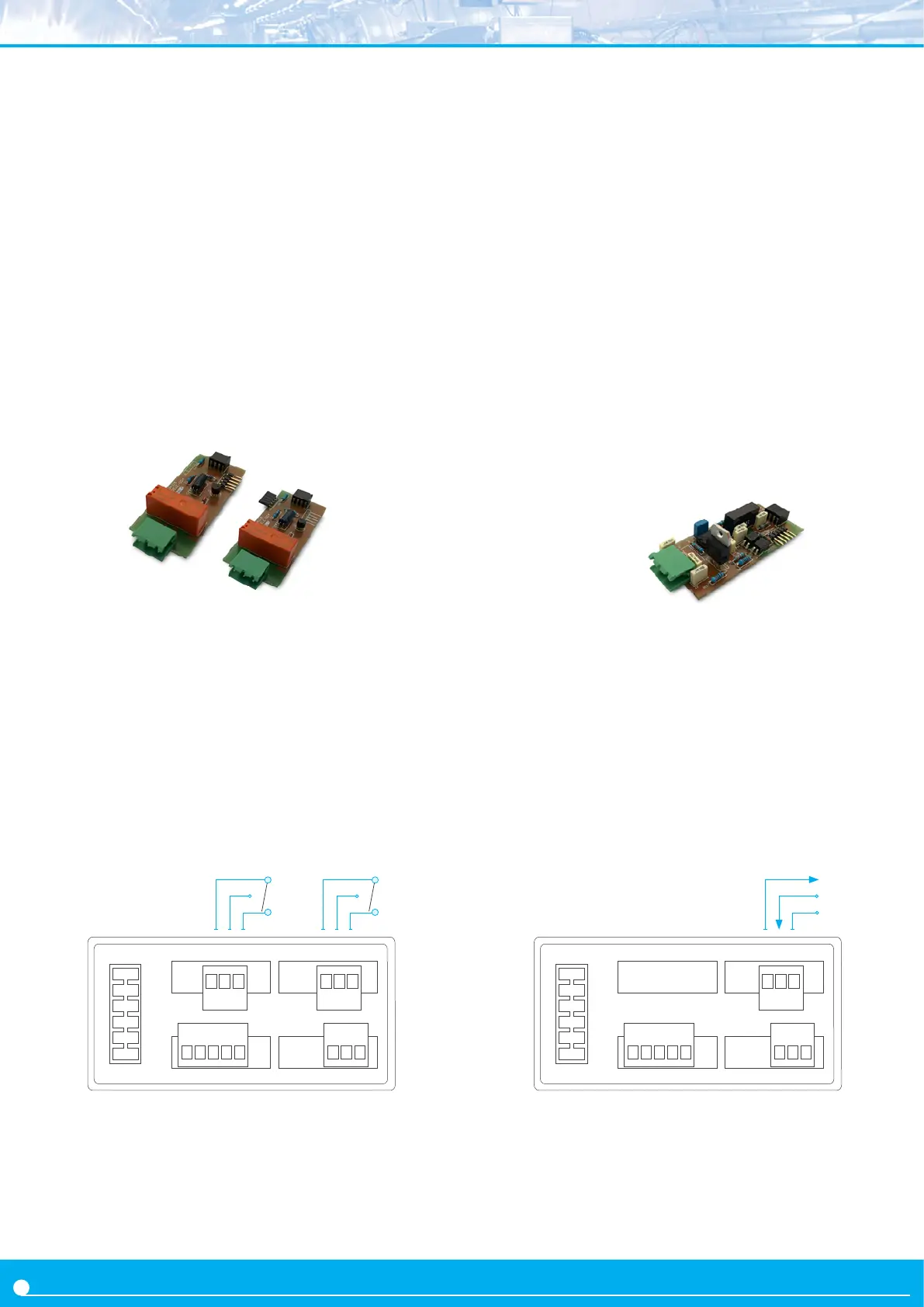
The A1 (and A2) modules oer 1 relay output to be installed at slot
Opt.1 (module A2 at Opt.2). The relay installed at Opt.1 is controlled
by alarm 1, and is congured from the ‘Alarm 1’ (‘Alr1’) menu ex-
plained at secon 1.29.3. The relay installed at Opt.2 is controlled
by alarm 2, and is congured from the ‘Alarm 2’ (‘Alr2’) explained
at secon 1.29.3. Relay with 3 contacts (Common, Normally closed,
Normally open) accepng voltages up to 250V @8A.
The A1 and A2 modules can be ordered installed in to a Series C in-
strument or standalone for later installaon, as they do not require
soldering or special conguraon..
2. Output and control modules
2.1 Modules A1 and A2 (relay output)
2.2 Module M1 (analog output)
Opt.1Opt.2
Terminal A, G Common
Terminal B, H NO - Normally open
Terminal C, I NC - Normally closed
Power
G H I A B C
Signal
The M1 module oers 1 analog output at 4/20 mA, isolated, to be
installed at slot Opt1.
The 4/20 mA output signal is fully scalable, both with posive and
negave slopes, and is proporonal to the reading of the instrument.
The mA output can be connected to work in acve loop (the module
provides the power of the loop) or passive mode (the power of the
loop is not provided by the instrument)
Connecons
For an acve 4/20 mA loop, connect terminal A (‘Vexc +15 Vdc’) as
current output and terminal B (‘Signal in mA’) as return of current.
For a passive 4/20 mA loop, connect terminal B (‘signal in mA’) as
current output and terminal C (‘GND’) as return of current.
Terminal A Vexc +15 Vdc
Terminal B Signal in mA
Terminal C Common
Output signal 4/20 mA (acve and passive)
Acve output connect terminal A (+15 Vdc) and B (mA)
R
L
<350 R
Passive output connect terminal C (GND) and B (mA)
R
L
< 700 R
Accuracy <0.5% FS
Response me <100 mSeg. + meter response me
Isolaon 1000 Vdc
Slots allowed Opt.1
Type of relay 3 contact relay (NC, NO, common)
Current maximum 8 A per relay (resisve load)
Voltage maximum 250 Vac connuous
when switching power lines, with overvoltage category 3, maximum switch-
ing voltage is 150Ve to comply with CE safety requirements
.
Isolaon 3500 Ve
Type of terminal plug-in screw terminal, pitch 5.08 mm
Slots allowed Opt.1 for A1 module
Opt.2 for A2 module
NC
Com.
NO
A B C
Opt.1
Common
Vexc
4/20 mA
NC
Com.
NO
PowerSignal
 Loading...