FEMA ELECTRÓNICA . Series C . C40-D
2
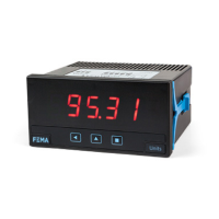
1. Panel meter C40-D
Mulsignal 96 x 48 mm panel meter, for OEM applicaons
Mulsignal digital panel meter in 96 x 48 mm size (1/8 DIN), for OEM
applicaons. Accepts AC and DC voltage signals from mV up to 600 V
and currents up to 5 A (AC measures in True RMS), process signals
(mA and Vdc) with excitaon voltage included, thermocouples K, J,
E, N, L, R, S, B, T and C, resisve temperature probes (Pt100, Pt500,
Pt1000, Ni100, Ni200, Ni1000, PTC and NTC), resistances, potenom-
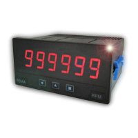
eters and frequency. Scalable reading with 4 digits up to 9999 / -1999
with congurable decimal point. Two independent alarms, congu-
rable as maximum or minimum, with hysteresis and setpoint.
Oponal 1 or 2 relay outputs, 4/20 mA isolated analog output, and
Modbus RTU isolated serial communicaons.
Front protecon IP50, with oponal IP65. Connecons with plug-in
screw terminals.
Index
1. Panel meter C40-D . . . . . . . . . . . . . . . . . . . . . . . 2
1.1 How to order . . . . . . . . . . . . . . . . . . . . . . . . 2
1.2 Front view . . . . . . . . . . . . . . . . . . . . . . . . . . 3
1.3 Rear view . . . . . . . . . . . . . . . . . . . . . . . . . . 3
1.4 Power connecons . . . . . . . . . . . . . . . . . . . . . 3
1.5 Signal connecons . . . . . . . . . . . . . . . . . . . . . 3
1.6 Mechanical dimensions (mm) . . . . . . . . . . . . . . . 3
1.7 Installaon and start-up . . . . . . . . . . . . . . . . . . 3
1.8 Technical specicaons . . . . . . . . . . . . . . . . . . 4
1.9 Internal jumpers . . . . . . . . . . . . . . . . . . . . . . 5
1.10 Measuring AC voltages and AC currents. . . . . . . . . 6
1.11 Measuring DC voltages and DC currents . . . . . . . . 7
1.12 Measuring thermocouples . . . . . . . . . . . . . . . . 8
1.13 Measuring with Pt and Ni probes . . . . . . . . . . . . 9
1.14 Measuring with NTC probes . . . . . . . . . . . . . . . 10
1.15 Measuring with PTC probes . . . . . . . . . . . . . . . 10
1.16 Process measures . . . . . . . . . . . . . . . . . . . . .11
1.17 Measuring frequency . . . . . . . . . . . . . . . . . . .11
1.18 Measuring resistances . . . . . . . . . . . . . . . . . . 12
1.19 Measuring potenometers. . . . . . . . . . . . . . . . 12
1.20 ‘Fast access’ menu . . . . . . . . . . . . . . . . . . . . 13
1.21 Scaling . . . . . . . . . . . . . . . . . . . . . . . . . . .13
1.22 Oset reading . . . . . . . . . . . . . . . . . . . . . . .13
1.23 ‘Eco’ mode . . . . . . . . . . . . . . . . . . . . . . . . . 13
1.24 External control . . . . . . . . . . . . . . . . . . . . . .13
1.25 Second scaling . . . . . . . . . . . . . . . . . . . . . . . 13
1.26 To open the instrument. . . . . . . . . . . . . . . . . . 14
1.27 How to operate the menus. . . . . . . . . . . . . . . . 15
1.28 Messages and errors . . . . . . . . . . . . . . . . . . . 15
1.29 Conguraon menu. . . . . . . . . . . . . . . . . . . . 16
1.29.1 Input signal ranges . . . . . . . . . . . . . . . . . . 16
1.29.2 Scaling . . . . . . . . . . . . . . . . . . . . . . . . . 17
1.29.3 Alarms . . . . . . . . . . . . . . . . . . . . . . . . . 17
1.29.4 Fast access . . . . . . . . . . . . . . . . . . . . . . .18
1.29.5 Super fast access . . . . . . . . . . . . . . . . . . . 18
1.29.6 External control . . . . . . . . . . . . . . . . . . . .18
1.29.7 Menu ‘Tools’ . . . . . . . . . . . . . . . . . . . . . . 19
1.29.8 Conguring the opons. . . . . . . . . . . . . . . . 21
1.30 Full conguraon menu . . . . . . . . . . . . . . . . . 22
1.31 Precauons on installaon . . . . . . . . . . . . . . . .25
1.32 Factory conguraon . . . . . . . . . . . . . . . . . . .25
1.33 Warranty . . . . . . . . . . . . . . . . . . . . . . . . . . 25
1.34 CE declaraon of conformity . . . . . . . . . . . . . . . 25
2. Output and control modules . . . . . . . . . . . . . . . . . 26
2.1 Modules A1 and A2 (relay output) . . . . . . . . . . . . 26
2.2 Module M1 (analog output) . . . . . . . . . . . . . . . . 26
2.3 Module S1 (Modbus RTU) . . . . . . . . . . . . . . . . .27
3. Other opons . . . . . . . . . . . . . . . . . . . . . . . . . . 28
3.1 Opon NBT . . . . . . . . . . . . . . . . . . . . . . . . . 28
3.2 Opon 65 . . . . . . . . . . . . . . . . . . . . . . . . . .28
3.3 Opon ‘customized’ . . . . . . . . . . . . . . . . . . . . 28
4. Accessories . . . . . . . . . . . . . . . . . . . . . . . . . . .29
4.1 Adapter DRA-M . . . . . . . . . . . . . . . . . . . . . . . 29
4.2 Adapter KA96 . . . . . . . . . . . . . . . . . . . . . . . .29
4.3 Protector KIP . . . . . . . . . . . . . . . . . . . . . . . . 29
4.4 WME wall housing . . . . . . . . . . . . . . . . . . . . . 29
4.5 THM benchtop housing . . . . . . . . . . . . . . . . . . 29
4.6 Set of units (included) . . . . . . . . . . . . . . . . . . . 29
Instrument designed for industrial use, highly exible, allows for in-
tegraon in mulple applicaons, reduced cost, excellent quality and
oponal customizaon available.
• ‘Fast access’ menu at front key UP (5) congurable for fast access
to alarm setpoints (see secon 1.20).
• ‘Eco’ mode reduces power consumpon
(see secon 1.23).
• Simplied scaling conguraon (see secon 1.21).
• Funcon ‘external control’ to acvate with a contact a predened
funcon (second scaling, decimal point, reading ‘hold’, ‘tare’, memo-
ry of maximum or minimum) (see secon 1.24).
• 5 congurable brightness levels (see secon 1.29.7).
1.1 How to order
C40 D
Model Power
-
Opon 1
U - - -
-A1 (1 relay)
-M1 (analog output)
-S1 (Modbus RTU)
-(empty)
-U (18-265 Vac/dc)
Others
-NBT
(
no front keypad
)
-65 (front IP65)
-(empty)
-
Opon 2
-A2 (1 relay)
-(empty)
Customizaon
-XXXX
(customized)
-(empty)
-
Series