Do you have a question about the Fema M60-C1 and is the answer not in the manual?
Guide for specifying model code, power, and optional modules.
Details the 5 selectable impulse counting modes and their features.
Explains the 2 selectable ratemeter modes and frequency measurement.
Describes the periodmeter mode and its signal period measurement.
Lists key functions like Fast access, SLOW/FAST modes, and alarms.
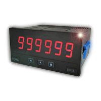
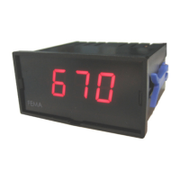
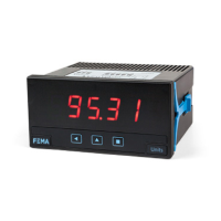
Identifies front panel components including display, buttons, and indicators.
Details power input requirements and fuse recommendation.
Provides typical connections and settings for various sensor types.
Shows terminal layout for rear connections and optional modules.
Explains input signal connections for channels A, B, and reset.
Comprehensive list of electrical, mechanical, and environmental specifications.
Provides panel cut-out and overall dimensions for installation.
Explains how the instrument detects trigger levels for inputs.
Describes how cycles are counted and stored in memory.
Details the special mode for low-frequency applications.
Details the special mode for high-frequency counting.
Explains navigation of configuration and fast access menus.
Lists common error codes and their meanings shown on display.
Overview of the instrument's extensive configuration menu structure.
Steps for initial configuration of function, decimal point, and sensor.
Specific settings for the 'Counter' mode (cn.1).
Specific settings for the 'Counter quadrature' mode (cnq.2).
Specific settings for the 'Counter + inhibition' mode (cnl.3).
Specific settings for 'Counter + control add/substract' mode (cnc.4).
Specific settings for the 'Counter differential' mode (cnd.5).
Specific settings for the 'Ratemeter' mode (rt.6).
Specific settings for 'Ratemeter quadrature' mode (rtq.7).
Specific settings for the 'Periodmeter' mode (Prd.8).
Detailed sensor settings, excitation voltage, and trigger level.
Configuration of up to 3 independent relay alarms with setpoints.
How to select and access frequently used functions via the UP key.
Shortcut for single-function access in fast access menu.
Configures instrument startup delay and reset behavior.
Assigns functions like 'No function', 'Front reset', 'Alarm unlock' to the LE key.
Configures display behavior for over/underrange conditions.
Controls the display of leading zeros on the instrument.
Sets a 6-digit password to protect configuration menu access.
Resets the instrument to its default factory settings.
Displays the current firmware version installed in the module.
Adjusts the intensity of the front LEDs for optimal visibility.
Accesses configuration menus for optional modules installed in slots.
Default settings for counter, ratemeter, and periodmeter modes.
Instructions for opening the instrument housing to access internal modules.
Explanation of the instrument's modular design and module placement.
Safety guidelines and installation recommendations for safe operation.
Details the product's manufacturing defect warranty period and terms.
Statement of compliance with EMC and low voltage directives.
Describes the 1-relay output module for alarm signaling.
Details the analog output module (4-20mA / 0-10V).
Explains the Modbus RTU communication module for data transfer.
Describes the RS-485 ASCII communication module.
Details the RS-232 ASCII communication module.
Describes relay modules with 2, 4, or 6 outputs.
Describes instruments without a front keypad, requiring panel removal for config.
Details front IP65 protection with sealing of front filter clips.
Describes the green LED digits option for enhanced visibility.
Benchtop housing with power connector and fuse holder.
Adapter plate for 96x96mm panel mounting of 96x48mm instruments.
Adapter for DIN rail mounting of panel meters.
Front IP65 protector for panel meters to enhance environmental resistance.
| Brand | Fema |
|---|---|
| Model | M60-C1 |
| Category | Measuring Instruments |
| Language | English |