FEMA ELECTRÓNICA . Series M . M60-C1
22
Type of relay 3 contact relay (NC, NO, common)
Current maximum 8A per relay (resisve load)
Voltage maximum* 250 Vac connuous
Type of terminal plug-in screw terminal, pitch 5.08 mm
Slots allowed ‘Opt.1’, ‘Opt.2’, ‘Opt.3’ (see secon 1.23)
Output ranges 4/20 mA acve, 4/20 mA passive 0/10 Vdc
Accuracy (at 25 ºC) <0.1% FS
Isolaon 1000 Vdc
Slots allowed ‘Opt.1’, ‘Opt.2’, ‘Opt.3’ (see secon 1.23)
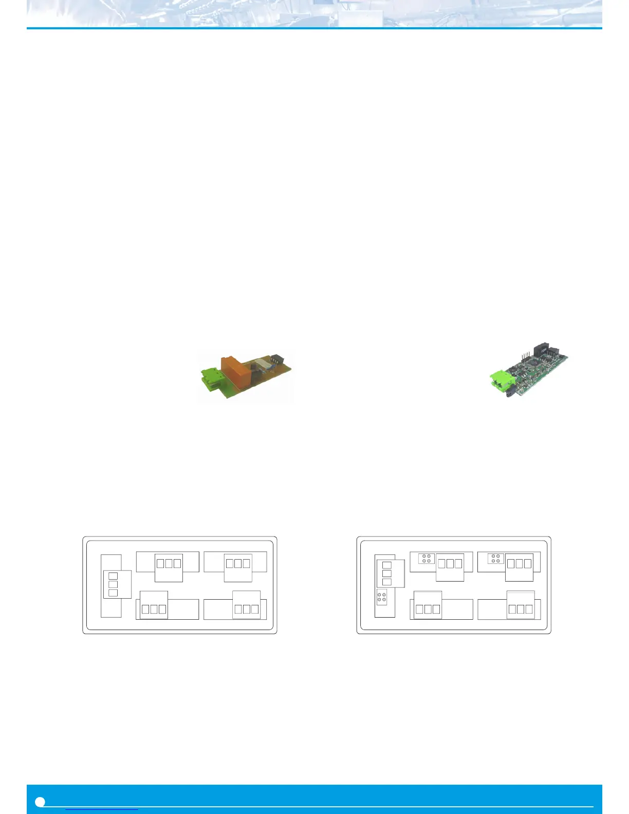
The R1 module provides 1 relay output to M Series panel meters.
Up to a maximum of 3 R1 modules can be installed in a single instru-
ment (3 relays).
Note : for more than three relays per instrument or larger relay den-
sity per module, see special modules R2, R4 and R6 at secon 2.6.
Relays with 3 contacts each (common, normally closed, normally
open), with switching capability up to 250V @ 8A.
Modules R1 are congured from the ‘ALr1’, ‘ALr2’ and ‘ALr3’ alarm
menus of the panel meter. The ‘ALrX’ menus provide conguraon
for main setpoint, hysteresis, independent acvaon and deacva-
on delays, and a second setpoint to create windowed alarms.
Modules R1 are installed on slot ‘Opt.1’, ‘Opt.2’ or ‘Opt.3’ (see sec-
on 1.23) and are congured from instruments front keypad.
The R1 module can be ordered pre-installed into a M Series panel
meter, or standalone for delayed installaon, as they do not require
soldering or special conguraon.
2. Output and control modules
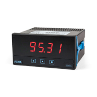
2.1 Module R1 2.2 Module AO
Terminal A Common
Terminal B NO - Normally Open
Terminal C NC - Normally Closed
Opt.2
Opt.1
Opt.3
Power
A B C A B C
A B C
Signal
The AO module provides 1 analog output with 4/20 mA or 0/10 Vdc
congurable output range. Output current loop congurable as ac-
ve (the instrument provides the excitaon for the loop) or passive
(the loop is externally powered). Signal output proporonal to the
instruments reading. Fully congurable scaling, in direct (posive
slope) or inverse (negave slope) scaling.
Up to a maximum of 3 analog output modules can be installed in a
single instrument, all outputs isolated between them and isolated
from the power and input signal circuits.
Conguraon from instrument front keypad, through menu entries
‘Opt.1’, ‘Opt.2’ or ‘Opt.3’, depending on the posion the module is
installed (see secon 1.23).
The RTU module can be ordered pre-installed into a M Series panel
meter, or standalone for delayed installaon, as it does not require
soldering or special conguraon.
Terminal A Vexc
Terminal B Signal in mA or Vdc
Terminal C GND
Jumper M closed for mA
Jumper V closed for Vdc
M V A B C
M V
A B C
M V A B C
Opt.2Opt.1
Opt.3
PowerSignal
For more informaon see document 3510_SERIES-M_MODULE-
R1_i.PDF
For more informaon see document 2654_SERIES-M_MODULE-
AO_i.PDF