FEMA ELECTRÓNICA . Series C . C40-D
17
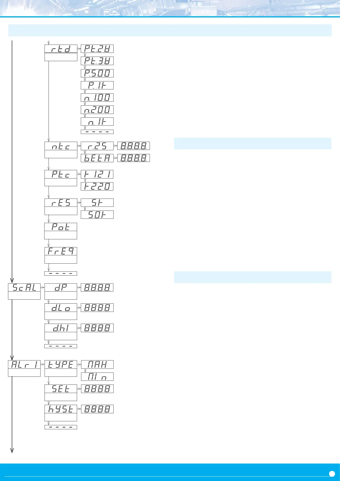
1.29 Conguraon menu (cont.)
Resistance
range 0 to 5 K
range 0 to 50 K
Scale the reading at the ‘Scaling’ (‘ScAL’) menu. Temperature ranges
(thermocouples, Pt and Ni probes, NTC and PTC probes) have direct
temperature indicaon and are not scalable.
To congure the scaling, enter the ‘Decimal point’ (‘dP’) parameter
and select the desired posion for the decimal point, using key ‘LE’
(3).
Then congure at the ‘Display Low’ (‘d.Lo’) parameter the reading
value associated to the low signal range and congure at the ‘Display
High’ (‘d.Hi’) parameter the reading value for the high signal range.
For more informaon see secon 1.21.
1.29.2 Scaling
Setpoint
Hysteresis
Alarm typeAlarm 1
The instrument has 2 independent and congurable alarms.
Control the independent acvaon of relays A1 installed (oponally)
at slots 1 and 2 (see secon 2.1) from menu entries ‘Alarm 1’ (‘ALr1’)
and ‘Alarm 2’ (‘ALr2’). Alarms control also the acvaon of front leds
‘1’ and ‘2’ located as indicated at secon 1.2.
To congure the alarms, enter at the alarm menu (‘ALr1’, or ‘ALr2’)
and congure the following parameters :
• at the ‘Alarm type’ (‘TypE’) parameter select alarm as as a max-
imum type alarm (‘MAX’) or a minimum type alarm (‘MIn’). The
maximum type alarm (or minimum type) acvates when the dis-
play value is higher (or lower) than the setpoint value.
• at the ‘Setpoint’ (‘SEt’) parameter enter the value for the alarm
acvaon point. This parameter is eligible for conguraon through
the ‘Fast access’ menu (see secon 1.20).
• congure the hysteresis value at ‘Hysteresis’ (‘hySt’). The hys-
teresis applies to the deacvaon process of the alarm. The alarm
deacvates when the reading has passed the setpoint value plus
the hysteresis value. Hysteresis helps to avoid repeve switching
of the alarm relays, due to uctuang input signals around the set-
point.
1.29.3 Alarms
Ni1000
PTC probes
KTY 210 and 220 family
KTY 121 family
Scaling
Decimal point
Display Low
Display High
NTC probes
res. at
25º
beta
RTD probes
Pt1000
Ni100
Ni200
Pt100 2 wires
Pt100 3 wires
• ‘Resistance’ (‘rES’) - select 5 K for a measuring range from 0 to
5 KOhms or select 50 K for a measuring range of 0 to 50 KOhms.
For a manual compensaon for the error introduced by the signal
wires, see parameter ‘Oset reading’ (‘oFFS’) (see secon 1.22).
• ‘Potenometer’ (‘Pot’) - potenometer measure has a single
range, valid for any potenometer with nominal value between
500 R and 20 K.
• ‘Frequency’ (‘FrEq’) - frequency measure has no selectable rang-
es. The instrument reads frequency up to 100 Hz, within accuracy
specicaons. For more informaon on frequency measuring see
secon 1.17.
Potenometer
pt500
Frequency
 Loading...