FEMA ELECTRÓNICA . Series C . C40-D
8
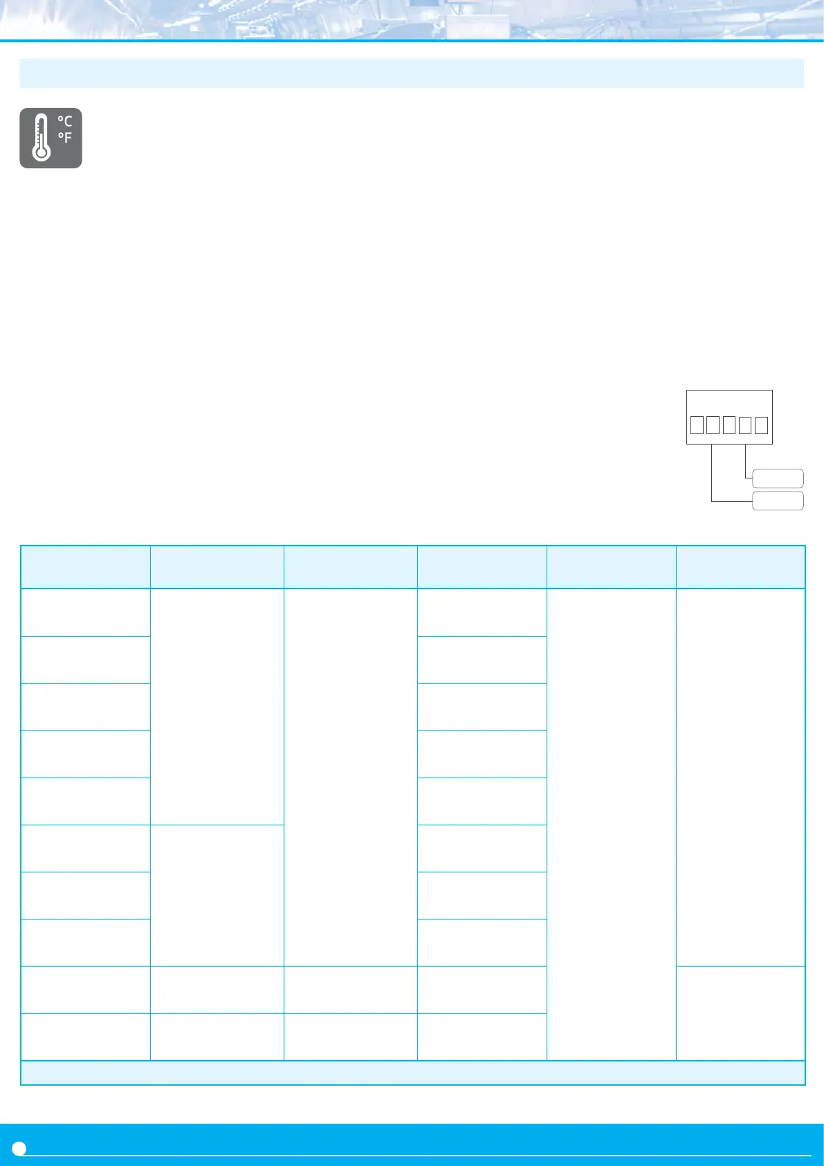
1.12 Measuring thermocouples
• Thermocouples accepted
The instrument accepts direct connecon of thermo-
couples type K, J, E, N, L, R, S, B, T and C.
• Temperature ranges and total error
Temperature ranges and total error for each type of thermocouple
are indicated on ‘Table 10’ below.
• Cold juncon compensaon
The thermocouple cold juncon is automacally compensated by
the instrument. The automac compensaon can be disabled from
the conguraon menu.
• Resoluon and units
The instrument resoluon when measuring thermocouples is 1º.
Reading can be congured in ºC (degrees Celsius) or ºF (degrees
Fahrenheit).
• Sensor break detecon
In case of sensor break, the instrument will show ‘h.ovr’ or ‘h.udr’
(see secon 1.28) depending on the broken cable.
Thermocouple
Jumper ‘S’
(see secon 1.9)
Jumper ‘T’
(see secon 1.9)
Range in ºC
(in ºF)
Connecon
(
terminals)
Total error
(cold juncon included)
Thermocouple
K
E
4-5
-100 / 1350 ºC
(-148 / 2462 ºF)
2 (tc +)
4 (tc -)
<3 º
Thermocouple
J
-100 / 1200 ºC
(-148 / 2192 ºF)
Thermocouple
E
-100 / 1000 ºC
(-148 / 1832 ºF)
Thermocouple
N
-100 / 1300 ºC
(-148 / 2372 ºF)
Thermocouple
L
-100 / 900 ºC
(-148 / 1652 ºF)
Thermocouple
R
E J
0 / 1768 ºC
(32 / 3214 ºF)
Thermocouple
S
0 / 1768 ºC
(32 / 3214 ºF)
Thermocouple
T
-100 / 400 ºC
(-148 / 752 ºF)
Thermocouple
C E
0 / 2300 ºC
(32 / 4172 ºF)
<5 º
Thermocouple
B E J
700 / 1820 ºC
(1292 / 3308 ºF)
Table 10 - Temperature ranges for thermocouples
tc +
tc -
12345
• Compensated cable
To correctly measure a thermocouple signal, always use compensat-
ed cable, of the thermocouple used, to connect the instrument and
the thermocouple.
• Response mes
The response me to a signal step is 300 mSeconds, independent of
the signal range selected.
• Terminal 5 ‘mulfuncon’ - External control
Terminal 5 remains congured as ‘EK’ external control funcon. See
secon 1.9 for a list of available funcons.
• Start-up, connecons and jumpers
For instrument start-up follow the steps listed at secon 1.7. Signal
connecons are indicated at secon 1.5. Locaon for internal jump-
ers is indicated at secon 1.9.
See below connecons for thermocouple :
 Loading...