FEMA ELECTRÓNICA . Series C . C40-D
5
5
6
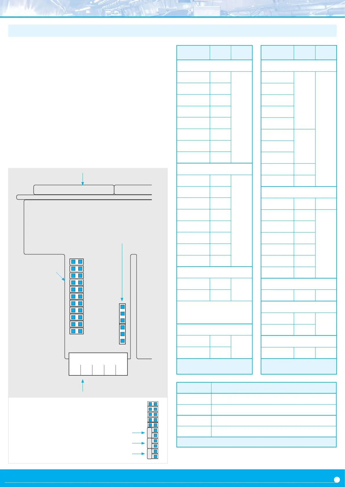
Input signal terminals
Jumpers ‘S’ for signal
range selecon
Displays
F
E
G
H
I
J
D
B
C
A
K
1.9 Internal jumpers
Internal jumpers ‘S’ are associated to the signal range. The posion
of internal jumper ‘T’ assigns the funcon of the mulfuncon termi-
nal 5. At ‘Table 2’ see a list of signal ranges and associated jumper ‘S’
and ‘T’. At Table 3 see the posion for jumper ‘T’ associated to each
funcon of the mulfuncon terminal 5. To access the internal jump-
ers, open the housing as explained at secon 1.26. For addional
informaon on each signal range see the following secons :
• Ranges for AC voltages and currents, see secon 1.10
• Ranges for DC voltages and currents, see secon 1.11
• Ranges for thermocouples, see secon 1.12
• Ranges for Pt and Ni probes, see secon 1.13
• Ranges for NTC probes, see secon 1.14
• Ranges for PTC probes, see secon 1.15
• Ranges for process signals, see secon 1.16
• Ranges for frequency signals, see secon 1.17
• Ranges for resistance measures, see secon 1.18
• Ranges for potenometer measures, see secon 1.19
Range Jumpers
‘S’
Jumper
‘T’
AC voltages and currents
~ 600 Vac
G I
4-5
~ 200 Vac
I
~ 20 Vac
A I
~ 2 Vac
B I
~ 200 mVac
C I
~ 60 mVac
E I
~ 5 Aac I
~ 20 mAac D I
DC voltages and currents
±600 Vdc
G
4-5
±200 Vdc
- - -
±20 Vdc
A
±2 Vdc
B
±200 mVdc
C
±60 mVdc
E
±5 Adc - - -
±20 mAdc D
Process
4/20 mA D
1-2
*
0/10 Vdc A
* jumper 1-2 to acvate Vexc.
Select 4-5 to acvate funcon ‘EK’
Resistances
0 to 5 K F H K
4-5
0 to 50 K F K
Table 2 - Jumpers ‘S’ and ‘T’ and signal
ranges
Range Jumpers
‘S’
Jumper
‘T’
Thermocouples
Tc. K
E
4-5
Tc. J
Tc. E
Tc. N
Tc. L
Tc. R
E J
Tc. S
Tc. T
Tc. C
E
Tc. B
E J
Pt and Ni probes
Pt100
(3 wire)
F H J 5-6
Pt100
(2 wire)
F H
4-5
Pt500 F
Pt1000 F
Ni100 F H
Ni200 F H
Ni1000 F
NTC probes
NTC F K 4-5
PTC probes
KTY 121 F
4-5
KTY 210, 220 F H K
Potenometers
0/100 % A 2-3
Table 2 - Jumpers ‘S’ and ‘T’ and signal
ranges
Jumpers stored at
‘no contact’ posion
F
E
G
H
I
J
D
B
C
A
K
Jumpers not used can be stored for
future use by placing them at the
‘no contact’ posions indicated be-
low. Only the 3 posions indicated
are safe to store jumpers.
Jumpers ‘T’ Acve funcon at terminal 5
1 2 Vexc (excitaon voltage +15 Vdc) for process
2 3 Potenometer excitaon (+5 Vdc)
4 5 External control (‘EK’ funcon)
5 6 Pt100 third wire
Table 3 - Jumpers ‘T’ and funcon at mulfuncon terminal 5
2
1
3
5
4
6
Jumpers ‘T’ for terminal 5
funcon selecon
 Loading...