Pag 42
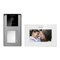
KIT
VIDEOPORTERO DIGITAL 5 HILOS
VIDEOPORTERO DIGITAL 5 HILOS
+
-
L
V+
V-
CT
+-
V+
V-
..........
..........
....
....
Vac
Ct
L
B
S
EXT.
INT.
C
B
No
+-
+12
Nc
JP2
Vo-
+A
-A
CT
-
+
L
Vi-
Vi+
106CI08C
J1 PRG
Vo+
CN2
1
2
HIGH RESOLUTION
FLAT MONITOR
10 Kohm
-+-+
12 Vdc
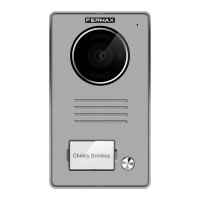
PLAC
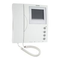
TELEFONO
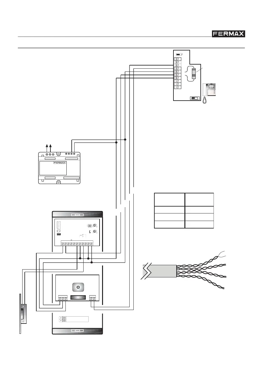
KIT WIRING DIAGRAM
A 10 Kohm resistance must be placed
between the monitor terminals + and L. A
bag with 5 resistances is included with
the kit.
mm
mm
mm
CROSS
SECTION
DISTANCE
(meters)
1 a 50
50 a 100
100 a 200
2,5
1,5
1
2
2
2
ADS KIT
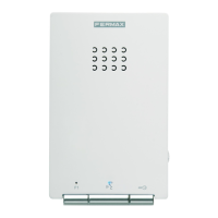
AMPLIFIER
CAMERA
NOTE: The power supply may be placed at an intermediate point in the installation.
Maximum distance from panel: 30 metres.
For distances over 100 metres or
additional equipment sets.
V+
+
-
L
V-
CAT 5 UTP 4 pair cable, up to a
maximum distance of 100
metres.
POWER
SUPPLY