Pag. 10
Technical Book
MDS
MDS
Audiodecoder 4 Ref.2424 & Audiodecoder 8 Ref.2425
These standard decoders are used for audio/video installations.
The telephones connected to a decoder are isolated from the rest of the installation (except the ones in the
same decoder). Any fault in a telephone will not affect any other in the installation, except the ones installed
in the same decoder (possibly affected).
Once programmed, the decoder receives the call code from the decoder BUS and generates a call signal
to the corresponding telephone if the code is acknowledged, connecting audio bus to this telephone. After
the conversation, decoders detect when telephone is hang up and cut communication.
Each decoder output (telephone connector) works as a standard City Panel 1AP101, with the corre-
sponding connections:
nº 1: power supply to microphone (electret type)
nº 2: audio from telephone to panel
nº 3: negative
nº 4: call signal
nº 6: audio from panel to telephone
The maximum amount of terminals to be connected to each output is 3 telephones (for the same apart-
ment). The more telephones installed, the lower the call sound.
PGM
BUS
- V
BUS
D2D1
62
6
2
13
422
1
2
6
3
4
1
63
4
1
6
3
4
5
768
AUDIO DECODER 8
DECODER DE AUDIO 8
DECODER Nº:
TELEFONOS / TELEPHONES
PGM
BUS
- V
BUS
M
A
D
E
I
N
S
P
A
I
N
FERMAX
REF. 2425
12 43
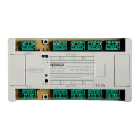
V connector (to synchronize
distributor in video installations)
Telephone connector
4 units in ref 2424
8 units in ref 2425
PC Programming connector
0,5 A protection fuse
Isodecoder Ref.2426
In addition to the audiodecoder features, isodecoders have individual isolation for each output. This means
that a failure in any telephone would not affect the rest of the installation, including telephones connected to
the same decoder. Moreover, isodecoders have extra features, such PANIC CALL terminal and activation
signal. Therefore, apart from the standard terminals that every decoder has, some extra terminals are
included for each output:
nº X: for special functions (to turn on a busy line LED in the telephones, generally)
nº P: panic call input (only in MDS-DIGITAL using panic call features)
D1
6
D2
2
2X
X
1+
3
6
4
P
2
X
+
1
P
6
34
X
1
AUDIO ISODECODER 4
ISODECODER AUDIO 4
TELEFO
NO
S / TELEPHO
NES
PGM
BUS
BUS
- V
REF. 2426
DECODER Nº:
MADE IN SPAIN
FERMAX
3
4
2
T
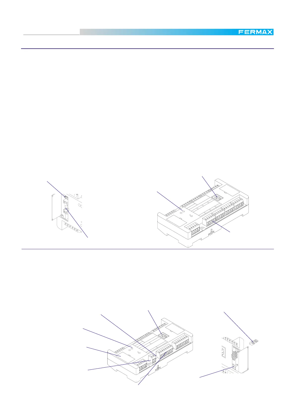
V connector (to synchronize
distributor in video installations)
Test jumpers:
T-Communicates telephone with the test handset
N-Normal operation.
Testing switch:
N-Handset connect with outdoor panel
T-Handset connect with internal telepone
selected with test jumpers.
Test handset jack
Test handset jack
X terminal (duplicated)
PC programming connector
and 0,5 A protection fuse
under the cover
LED indicator
is ON when the telephone is selected
Telephone connector
4 units
 Loading...